 Cart ( )
Push-pull Amplifier: Working Principle, Circuit Diagram
2024/10/16 18:21:25
Views:
If you are looking for a way to maximize the power of circuit while keeping signal intact, a push-pull amplifier is the best choice for you. It uses two transistors to share the work, not only increasing the output power, but also enhancing the clarity of the signal.
- What is a Push-pull Amplifier?
- Working Principle of Push-pull Amplifier
- Circuit Diagram of Push-pull Amplifier
- Key Features of Push-pull Amplifier Design
- Advantages and Disadvantages of Push-pull Amplifier
- Applications of Push-pull Amplifier
What is a Push-pull Amplifier?
Push-pull amplifiers use two active devices (such as transistors) working together, one responsible for amplifying the positive half cycle of the signal (push) and the other for handling the negative half cycle (pull). This configuration reduces distortion, improves efficiency, and provides higher output power compared to single-ended amplifiers.
Working Principle of Push-pull Amplifier
Push-pull amplifiers work by relying on two transistors alternately "pushing" and "pulling" signals. When the input signal is positive, a transistor (NPN) turns on and processes the amplification. When the input signal is negative, another transistor (PNP) takes over and amplifies the negative half. This division of work helps to reduce energy waste and reduce distortion.
what push pull amplifiers are most commomly used?
Class A Push-pull amplifier: Two transistors are always on, with high linearity but low efficiency.
Class B Push-pull amplifier: only one transistor is on at a time, increasing efficiency but causing cross distortion.
Class AB Push-pull amplifier: A balancing method in which two transistors are switched on simultaneously for a short time,reducing distortion and maintaining relatively high efficiency.
Circuit Diagram of Push-pull Amplifier
When you look at a typical circuit diagram of a complementary push pull amplifier, you'll see two main components: NPN and PNP transistors, resistors, and sometimes capacitors for signal filtering. Push-pull Amplifiers divide the input signal into positive and negative parts, each amplified by two transistors. The output is then recombined to form a stronger, clearer version of the input signal.
The key feature here is the ability to reduce cross distortion, which occurs when the signal moves from the positive half to the negative half. In a well-designed push-pull Amplifier, this distortion is minimized because both transistors operate simultaneously at the intersection.
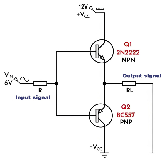
Typical Circuit Diagram of Push-pull Amplifier
Key Features of Push-pull Amplifier Design
When designing or using push-pull amplifiers, there are some important factors to consider:
- Efficiency: push and pull amplifier are more efficient at handling high power outputs, while Class AB amps have a better balance of efficiency and sound quality to better meet your needs for both.
- Power output: These amplifiers are suitable for driving large loads and are commonly used in audio amplification applications.
- Heat dissipation: Since the two transistors share the load, the heat is distributed, but a suitable heat sink is still needed to effectively manage the temperature.
- Trade-off: While push-pull amplifiers are effective at reducing distortion, they are more complex to design than single-ended amplifiers.
Advantages and Disadvantages of Push-pull Amplifier
Advantages:
More efficient: Especially in Class B or Class AB designs, push-pull amplifiers consume less power than single-ended amplifiers.
Reduced distortion: The dual-transistor configuration smooths out the output signal, making it ideal for high-fidelity audio applications.
High power capability: You will find these amplifiers in applications that require strong signal output, such as home theater systems or broadcasting.
Disadvantages:
Complex design: Circuits require careful design and matching of components to ensure smooth operation.
Cross distortion: In Class B push-pull amplifiers, cross distortion can occur, but the class AB push-pull amplifier class design can often effectively mitigate this problem.
Applications of Push-pull Amplifier
Push-pull amplifiers are widely used, especially where high sound quality or high power output is required.Common uses include:
Audio amplification: They are commonly used in stereo systems or amplifiers to drive speakers with minimal distortion.
RF (radio frequency) circuits: These amplifiers help efficiently transmit signals over long distances.
Power electronics: Used in power supplies and inverters to efficiently handle high currents.
In electronics, push-pull amplifiers play an important role because they are able to effectively amplify signals and minimize distortion. Whether you are designing audio systems or dealing with high power outputs, this amplifier can help you design more reliable and efficient circuits.
Frequently Asked Questions(FAQ)
1. why is it called Push-pull Amplifier
A push-pull Amplifier is so called because it uses two active devices (transistors) that alternately "push" and "pull" current in opposite directions to drive the load, thereby increasing efficiency and reducing distortion.
2. How to bias a Push Pull amplifier
To bias a push-pull Amplifier, you need to set a small voltage between the base of the transistor, usually using a diode or voltage divider, to make both transistors slightly on-when there is no input signal.
3. Why even harmonics are not present in Push pull Amplifier?
In push-pull Amplifiers, even harmonics cancel out due to the symmetrical operation of the two transistors handling opposite signal phases.
4. push pull vs open drain
The push-pull output actively drives high and low states, providing faster switching speeds and higher power. The open drain output only pulls the signal down, requiring an external resistor to pull it up. The use of push-pull increases speed and efficiency, while open-drain is ideal for shared signal lines and low-power applications.
Related Information


-

-
Phone
+86 135 3401 3447 -
Whatsapp
