 Cart ( )
IRF3205 MOSFET Datasheet: Pinout, Equivalents and Circuit
2025/1/4 16:43:28
Views:

How to build a 2000W inverter with a tiny transformer and 30 Mosfet IRF3205
What is a IRF3205?
The IRF3205 is an N-channel MOSFET designed for switching control and signal amplification applications in various electronic circuits. With its high withstand voltage of 55V, low on-resistance and high current handling capability of 120A, it is widely used in high power circuits such as power supplies, inverters and motor drives. Its low gate voltage requirement makes it compatible with 3.3V or 5V logic systems (such as Arduino) for a wide range of control and regulation circuits.
IRF3205 Specification
· Drain-Source Voltage (Vds): 55V
· Gate-Source Voltage (Vgs): ±20V
· Continuous Drain Current (Id): 120A (at 25°C)
· Rds(on): 0.047Ω (at Vgs = 10V)
· Total Gate Charge (Qg): 140nC
· Package: TO-220 (standard through-hole package), also available in SMD form for more compact applications.
· Power Dissipation: 150W
· Threshold Voltage: 2V to 4V (depending on the model)
IRF3205 Pinout and Pin Configuration
The IRF3205 MOSFET pinout consists of three main terminals: Gate, Drain, and Source, each serving a specific function in the transistor's operation.
Pin configuration:
- Pin 1 (Gate): The gate is used to control the current flowing through the MOSFET. When voltage is applied to this pin, it creates an electric field that turns the MOSFET on or off depending on the voltage relative to the source pin.
- Pin 2 (Drain): Current flows out of the MOSFET through the drain pin. This is where the load is connected in the circuit.
- Pin 3 (Source): Current enters the MOSFET through the source pin, which is typically grounded or connected to the negative side of the power supply in many applications.
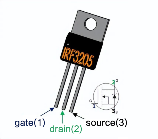
IRF3205 MOSFET Pinout

IRF3205 Symbol,Footprint,3D Model
IRF3205 MOSFET Applications and Circuits
The IRF3205 is a versatile transistor that can be used in a variety of high power applications, especially in circuits where efficient power switching is critical. The following are some common applications and example circuits for the IRF3205.
1. Motor Driver Circuits (H-Bridge)
The IRF3205 is commonly used in DC motor driver circuits, especially in H-bridge configurations. This setup allows precise control of motor speed and direction and is ideal for robotics, electric vehicles, and automation systems. Using four MOSFETs (two IRF3205s), the H-bridge provides bi-directional control, allowing the motor to rotate in forward or reverse and adjust its speed.
Example Circuit: IRF3205 H-Bridge Motor Driver
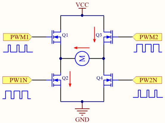
IRF3205 H Bridge Circuit Diagram
In this circuit, two IRF3205 MOSFETs are used to switch the direction of current flowing through the motor, controlling both forward and reverse motor rotation. The gate voltage is controlled by a microcontroller or driver circuit to precisely manage the direction and speed of the motor.
2. Battery Charger Circuit
The IRF3205 is commonly used in battery charging circuits due to its high current handling capability and low Rds (on). These features ensure minimal power loss and reduced heat generation, making the IRF3205 an excellent choice for efficient charging in applications such as electric vehicles or portable power systems.
Example Circuit: IRF3205 Battery Charger Circuit

IRF3205 Battery Charger Circuit Diagram
In this application, the IRF3205 MOSFET regulates the charging current to efficiently handle high currents and provide optimal management of the battery power system.
3. Inverter circuit (DC to AC conversion)
The IRF3205 is a key component in the inverter circuit for converting DC to AC power. This is critical in renewable energy systems such as solar or wind power, where the DC output of a solar panel or wind turbine must be converted to AC to be compatible with household electrical systems.
Example Circuit: IRF3205 Inverter Circuit
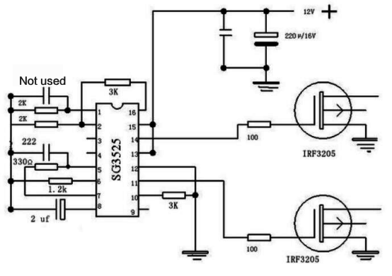
IRF3205 Inverter Circuit Diagram
In a typical DC to AC inverter, the IRF3205 MOSFET switches the DC voltage at high speed to produce an AC output. This configuration is critical to making renewable energy systems compatible with home AC power.
4. Power switching applications (Arduino integration)
The IRF3205 is also used in various power switching applications such as controlling motors, solenoids or high power LEDs. it is often integrated with Arduino in DIY projects where the microcontroller is used to control high current devices.
Example Circuit: IRF3205 Switching Circuit for Arduino
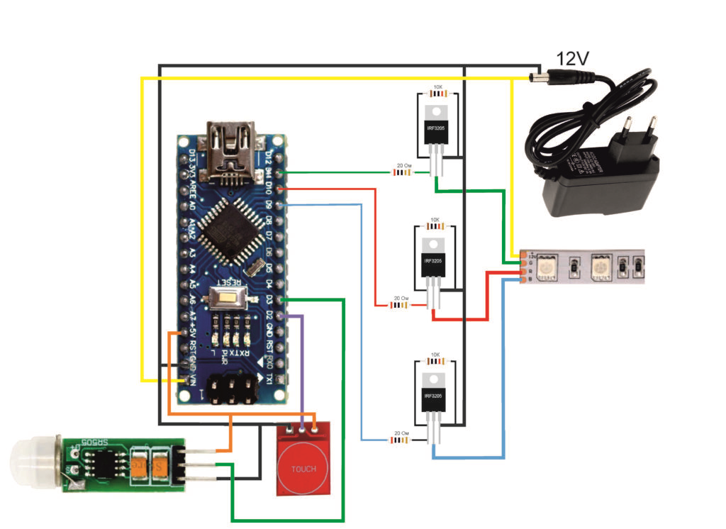
IRF3205 Arduino Switching Circuit Schematic
In this simple circuit, an IRF3205 MOSFET acts as a switch to turn a device on and off. the Arduino controls the MOSFET gate to turn a load on or off, making it easy to control high-power devices such as motors or LED strips.
5. Voltage Regulator Circuits
The IRF3205 is used in voltage regulator circuits to maintain a stable voltage for sensitive components. This is especially useful in power supply circuits that require precise voltage control to ensure proper operation of connected devices.
Example Circuit: IRF3205 Voltage Regulator Circuit

IRF3205 Voltage Regulator Circuit Diagram
In a voltage regulator configuration, the IRF3205 MOSFET is used to regulate the output voltage by switching the current based on system feedback to ensure that the component always receives the correct voltage, preventing overvoltage or undervoltage problems.
IRF3205 Equivalents and Substitutes
If you can't find the IRF3205, there are several MOSFETs that can be suitable alternatives:
IRF540N: A common N-channel MOSFET with a lower current rating (33A) compared to the IRF3205 (120A). Suitable for lower power applications, but may not be a direct replacement for the IRF3205 in high power designs.
IRLZ44N: Logic level MOSFET with low gate threshold voltage, ideal for direct interface with microcontrollers such as Arduino. With a current rating of 47A, it is lower than the IRF3205.
IRF1404: A higher current N-channel MOSFET rated at 175A for high power applications requiring more current than the IRF3205.
STP55NF06L: A MOSFET with similar electrical characteristics, often used as a direct replacement for the IRF3205 in power electronics applications.
IRF3205 P-channel equivalent: If a P-channel MOSFET is required, the IRF9540 is a suitable alternative with similar characteristics to the IRF3205.
Related Information


-

-
Phone
+86 135 3401 3447 -
Whatsapp
