 Cart ( )
A4988 Driver Insights: Perfect Your A4988 Motor Driver Setup
2024/10/8 14:19:13
Views:
The A4988 stepper engine driver is broadly utilized in several DIY electronics ventures for controlling bipolar stepper engines. Its ease of utilize, compact degree, and moo taken a toll make it a predominant choice for specialists and specialists alike. In this direct, we are going cover everything you wish to know approximately the A4988, counting its pinout, circuit associations, and how to utilize it with an Arduino. We'll too dive into its highlights and how to implement it in your ventures.
A4988 Stepper Motor Controller - Arduino & NodeMCU
Table of Contents
- What is the A4988 Driver?
- A4988 Motor Driver Setup
- A4988 Driver Price
- A4988 Dimensions
- Troubleshooting the A4988 Controller
- Conclusion
- Commonly Asked Questions
What is the A4988 Driver?
The A4988 may be a microstepping motor driver planned to control bipolar stepper motors. It gives up to 2A per coil with adequate cooling and works from an 8V to 35V control supply. This driver streamlines the errand of driving a stepper motor, with highlights like overcurrent security, overtemperature security, and short-to-ground security. It underpins full-step, half-step, quarter-step, eighth-step, and sixteenth-step resolutions, permitting for smooth and adjust control of motor improvements.
A4988 Pinout
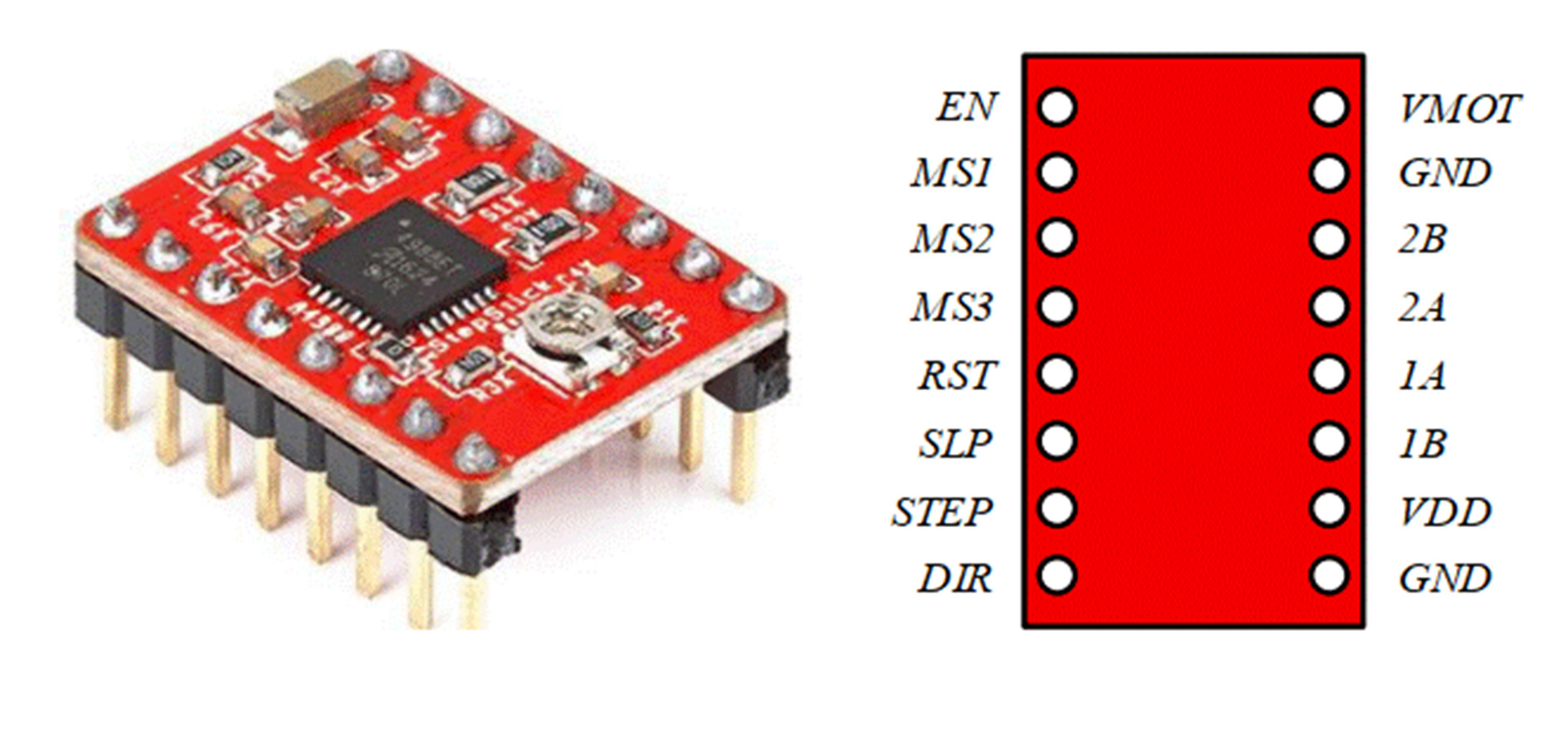
Understanding the pinout of the A4988 stepper engine driver is significant for making the correct affiliations in your circuit. Below is the A4988 Pinout that you will encounter:
The A4988 pinout allows for straightforward connections, which we will detail further as we walk through the process of setting up the circuit.
Key Features of the A4988 Driver
A4988 Motor Driver Setup
Setting up the A4988 motor driver can be a clear task on the off chance that you simply get it the basics of how it works. Here's a step-by-step coordinate for meddle the A4988 motor driver to an Arduino board and controlling a stepper motor.
Step 1: Gathering Components
Before you start, ensure you have the following components:
A4988 motor driver
Arduino board
Bipolar stepper motor (e.g., NEMA 17)
Power supply (12V recommended, 8V to 35V accepted)
Breadboard and jumper wires
Capacitor (100 µF recommended for VMOT pin)
Potentiometer (optional, for adjusting current limit)
Step 2: Setting up the Circuit
Below is an example of how to wire the A4988 circuit for controlling a stepper motor using an Arduino.
Circuit Diagram
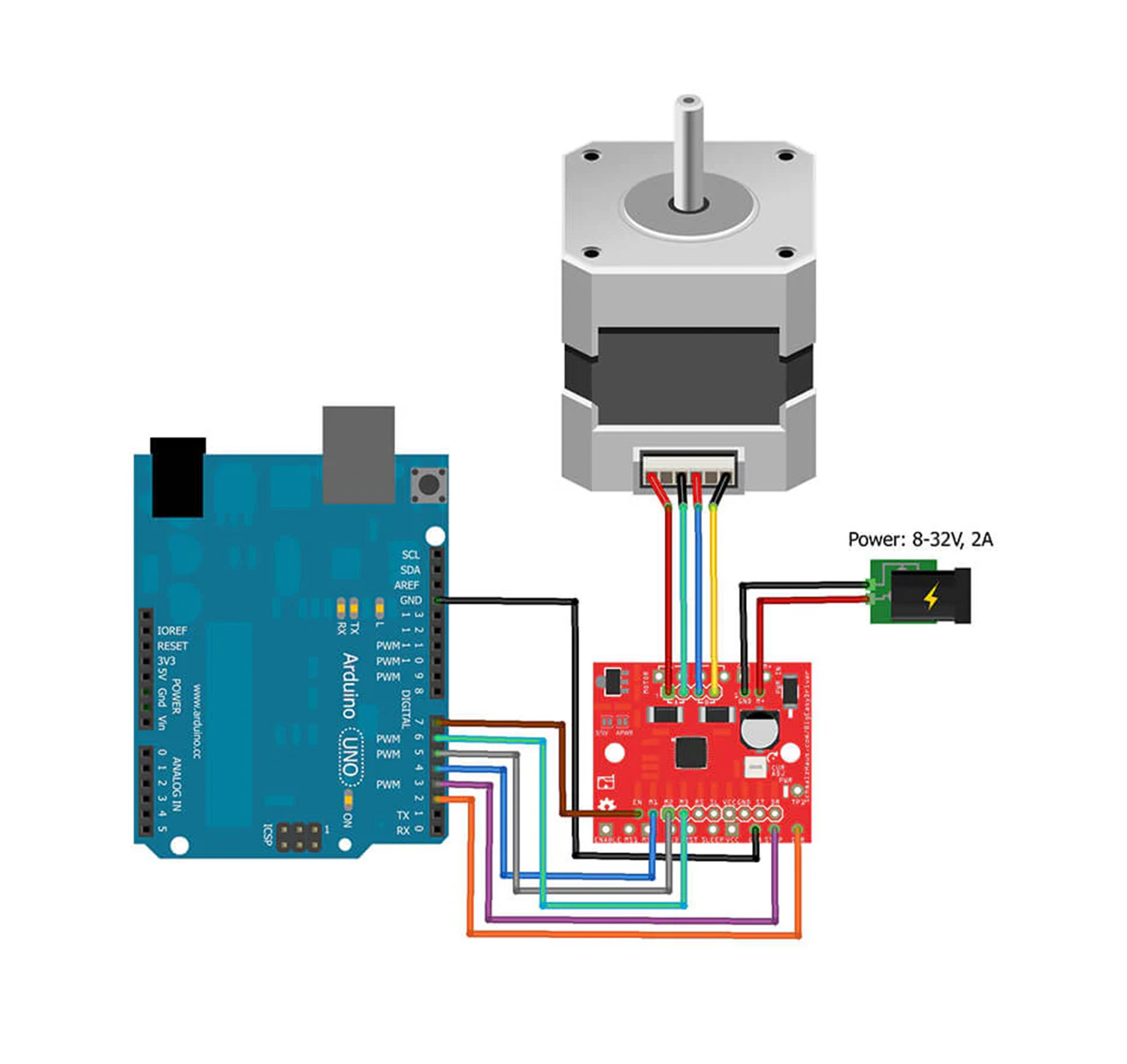
Wiring Instructions:
VMOT and GND: Interface VMOT to the positive terminal of your control supply and GND to the negative terminal. Be beyond any doubt to include a 100 µF capacitor over VMOT and GND to ensure the A4988 from voltage spikes.
Motor Connections: Interface the 2 coils of the stepper engine to 1A, 1B, 2A, and 2B at the A4988. Coil A is going to 1A and 1B, and Coil B is going to 2A and 2B.
VDD and GND: Interface the VDD adhere to the 5V adhere at the Arduino and the GND adhere to a floor adhere at the Arduino.
STEP and DIR: Interface the STEP and DIR pins on the A4988 to two computerized pins on the Arduino (e.g., Pin 2 for STEP and Pin 3 for DIR).
Microstepping Mode: Connect the MS1, MS2, and MS3 pins to ground or take off them detached for full-step mode. If you want microstepping, you can connect these pins to the logic voltage or ground in specific combinations as indicated in the A4988 datasheet.
Enable, Sleep, Reset: Connect the ENABLE, SLEEP, and RESET pins to the logic voltage (5V) to keep the driver enabled and out of sleep mode.
Step 3: Adjusting the Current Limit
The A4988 motor driver highlights a current restrain alteration through a little potentiometer on the driver board. This permits you to set the most extreme current that streams through your stepper motor coils, which is vital to anticipate overheating and guarantee the motor works easily. Follow these steps to adjust the current limit:
Turn off the power and remove the stepper motor.
Set your multimeter to the voltage measurement mode.
Place the black probe on the GND pin of the driver and the red probe on the potentiometer.
Turn the potentiometer slowly to adjust the voltage. Use the formula Imax = Vref / (8 * Rs) (where Rs is the sense resistor value, usually 0.05 ohms) to calculate the current limit.
Once the desired current limit is set, reconnect the stepper motor and power up the circuit.
A4988 Driver Price
One of the focuses of intrigued of utilizing the A4988 driver is its sensibility. The A4988 driver taken a toll customarily ranges between $1 to $5 per unit, depending on the vender and the amount obtained. Bulk buys may offer assist rebates, making the A4988 a cost-effective choice for bigger ventures.
A4988 Dimensions
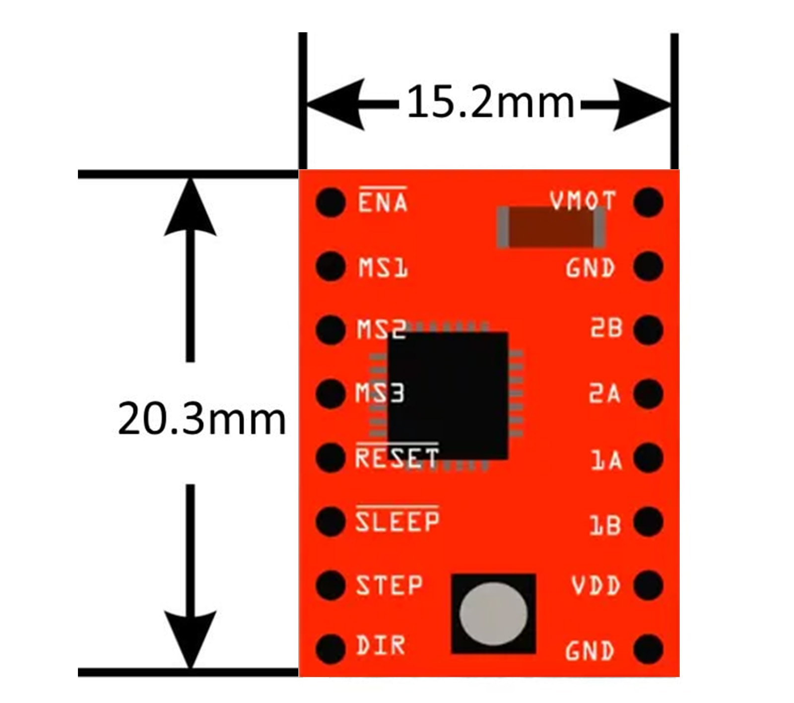
The A4988 dimensions are very compact, which makes it perfect for projects with constrained space. This small form factor allows for easy integration into compact projects without sacrificing performance.
Troubleshooting the A4988 Controller
When working with the A4988 controller, you may encounter a few issues. Below are some common troubleshooting steps:
Conclusion
The A4988 stepper motor driver may be a adaptable and sensible course of action for controlling bipolar stepper motors. With its coordinate pinout, direct STEP and DIR control, and adaptable current limit, the A4988 motor driver is idealize for a wide run of applications. Whether you're working on a 3D printer, CNC machine, or any other extend requiring exact motor control, the A4988 driver is an amazing choice.
This direct given a comprehensive outline of how to set up and utilize the A4988 driver, beside tips for wiring, coding, and investigating. Whether you're a tenderfoot or an experienced electronics devotee, you'll presently certainly utilize the A4988 in your ventures!
Commonly Asked Questions
What is the max current yield of the A4988?
Up to 2A per coil with appropriate cooling. Without it, viable current is lower to dodge overheating.How do you control microstepping with the A4988?
Utilize MS1, MS2, and MS3 pins to set full, half, quarter, eighth, or sixteenth steps based on the setup within the datasheet.Is the A4988 reasonable for 3D printers?
Yes, it's broadly utilized in 3D printers for controlling bipolar stepper engines with microstepping.What control supply is required for the A4988?
The A4988 works with an 8V to 35V supply. A 12V or 24V supply is common depending on your engine necessities.Related Information


-

-
Phone
+86 135 3401 3447 -
Whatsapp
