 Cart ( )
Wiring Diagram for 3-Wire AC Dual Capacitor
2024/12/19 17:59:03
Views:
How much do you know about 3 Wire AC Dual Capacitor Wiring Diagram? This article will explain in detail the content of this wiring diagram, from each interface description to the wiring steps will be explained, I believe that after reading this article, you will have a clearer understanding of this wiring diagram.
Wiring Diagram for Split AC Capacitor | Dual Capacitor | HVAC | Electrical
- Introduction
- Role of Capacitors
- Wiring Diagram Components
- Wiring Procedure
- Precautions
- 3-Wire AC Dual Capacitor Wiring Diagram
- Conclusion
Introduction
One of the devices that we can come across in our life that is related to this wiring diagram would be the air conditioner. The 3-wire AC dual capacitor wiring plays a vital role in the proper functioning of these electrical devices and motors. This type of configuration is used in HVAC systems or other equipment that drives both a fan and a hermetically sealed compressor, and the dual capacitor is a great addition to this type of configuration!
Role of Capacitors
There are two capacitors in this configuration, each with a different division of labor, so let's see what they are.
Starting And Running Capacitor Connections
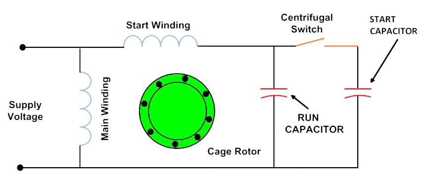
- Start Capacitor: When the motor starts, the start capacitor provides extra current to help the motor with startup resistance and is disconnected from the circuit once started.
- Run Capacitor: During motor operation, the run capacitor stays connected and provides a phase shift to allow the motor to increase efficiency and stabilize operational performance.
Wiring Diagram Components
We've learned a little bit about the double capacitor part, now let's look at the components of the wiring diagram.
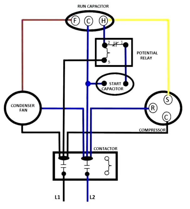
1. Common terminal (C)
The common terminal, labeled "C", connects to the common terminal of the capacitor. It is the bridge between the fan and the sealed compressor circuit, and is the core of the entire circuit.
2. Fan terminal (F)
The fan terminal is labeled "F" and is connected to the fan terminal of the capacitor. Provides power support to the fan motor for operation.
3. Compressor Terminal (H)
The compressor terminal is labeled "H" and is connected to the capacitor's compressor terminal. Ensure that the hermetic compressor motor can operate properly.
Wiring Procedure
The next step is the wiring procedure, please make sure that there is no misconnection.
1. Identify the ports
Check and verify the markings on the unit for the common (C), fan (F) and compressor (H) wires. Familiarize yourself with these markings and do not skip over them to avoid mistakes.
2. Port Connections
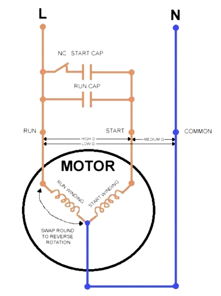
AC Capacitor Connection Diagram
First connect the common wire (usually black) to the common terminal (C) of the capacitor. Next connect the fan wire (brown) to the fan terminal (F) of the capacitor. Finally connect the compressor wire (yellow) to the compressor terminal (H) of the capacitor. The red wire is connected to the other side of the capacitor and is usually left unconnected. It's fine to connect whichever wire first, but to avoid confusion, it's recommended to connect them in the order I've just described to make it easier to check and verify.
3.Verification
Make sure that each wire is securely connected and verify that the wiring complies with the documentation provided by the equipment manufacturer.
It is recommended to use a multimeter to measure the resistance between the terminals to rule out short circuits or broken circuits.
Precautions
In order not to cause unnecessary trouble to your work, but also for your safety, please read the following carefully.
1. Before wiring, be sure to make sure that the power supply of the equipment is turned off, and it is recommended to use a multimeter to check the wiring to ensure that there is no residual voltage.
2. Please use brackets or screws to install the capacitor firmly before wiring to avoid loosening or damaging the capacitor due to vibration.
3. After the installation is completed, turn on the power and observe the operating condition of the device. If there is any abnormality, such as slow starting or excessive noise, you should immediately disconnect the power to check whether the wiring is correct.
4. Environmental factors such as high temperature, humidity or severe vibration may shorten the service life of the capacitors, please make sure that the installation environment meets the requirements, and choose a quality capacitor that meets UL810 and other safety standards.
5. The wiring diagram and capacitor selection should be in accordance with IEC or ANSI standards to ensure the electrical safety and stability of the equipment, which can make your work twice as effective.
3-Wire AC Dual Capacitor Wiring Diagram
Connection Diagram for AC Dual Capacitor
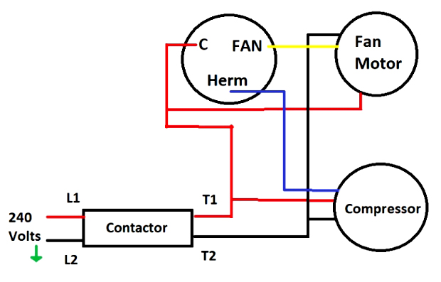
Dual Round HVAC Capacitor Connection Diagram
Conclusion
This is all about the 3-wire AC dual capacitor wiring diagram, please pay attention to the safety of the actual operation, be sure to refer to the equipment manufacturer's instructions provided by the document and industry standards, in order to minimize the possibility of wiring errors and operational failures, to protect the normal operation of the equipment.
Related Information


-

-
Phone
+86 135 3401 3447 -
Whatsapp
