 Cart ( )
Building a TDA2822M Circuit Using a TDA2822M Amplifier
2024/10/24 12:07:07
Views:
The TDA2822M is a widely used low-power amplifier IC that is ideal for building simple audio amplification circuits. It offers great flexibility and efficiency in small electronics projects, especially where space and power are limited. This article will walk you through the process of building the TDA2822M circuit and its configuration.
TDA2822M,Low voltage Dual channel Audio amplifier | hobby project | Free Circuit Lab
Table of Contents
- What is the TDA2822M?
- TDA2822M Amplifier Circuit Design Considerations
- Building the TDA2822M Amplifier Circuit
- TDA2822M Equivalent ICs
- Exploring the TDA2822M Datasheet
- Conclusion
- Commonly Asked Questions
What is the TDA2822M?
The TDA2822M is a dual-channel audio amplifier IC designed for applications requiring low power consumption, making it suitable for devices such as portable radios, recorders and small speaker systems. The IC has a wide range of supply voltages, making it adaptable for different audio applications.
TDA2822M Pinout Description
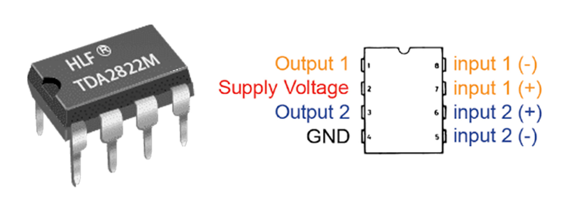
Knowing the TDA2822M pin layout ensures proper IC connection and avoids common problems such as reverse polarity or wrong grounding.
TDA2822M Key Features
- Low supply voltage
- Dual-channel output
- Low distortion and noise
- Compact design
- Internal thermal shutdown
- Short-circuit protection
Applications
- Portable audio devices
- Personal speaker systems
- Intercom systems
- Battery-powered audio amplifiers
TDA2822M Amplifier Circuit Design Considerations
When designing the TDA2822M amplifier circuit, several factors need to be considered to ensure its stable operation and high quality audio output:
- Power supply: Ensure that the power supply is stable and within the recommended range. Use decoupling capacitors to filter out noise from power lines.
- Input filtering: Use capacitors to filter the input signal to remove any unwanted noise.
- Heat dissipation: Although the TDA2822M has internal thermal protection, it is recommended to provide adequate heat dissipation, especially when driving larger loads.
- Speaker matching: Ensure that the speaker impedance matches the output requirements of the TDA2822M to avoid overloading the IC.
Building the TDA2822M Amplifier Circuit
TDA2822M microphone amplifier circuit
This is a microphone amplifier circuit that uses the TDA2822M chip to amplify the audio signal from the microphone (MIC1) and drive an 8-ohm speaker (SPKR1).
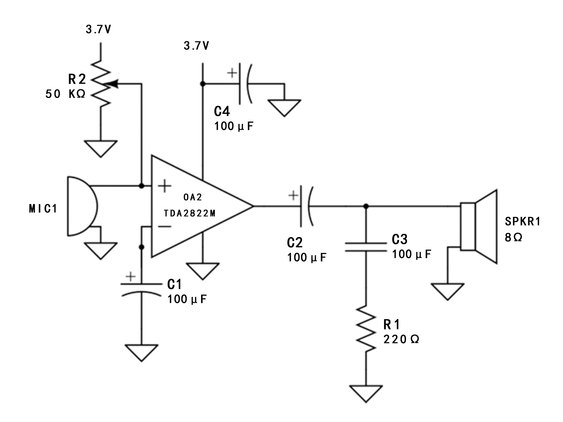
Circuit Description:
Powered by 3.7V, this circuit is ideal for portable voice amplification.
TDA2822M mono power amplifier circuit
This TDA2822m-based mono audio amplifier circuit uses simple components to amplify mono signals.
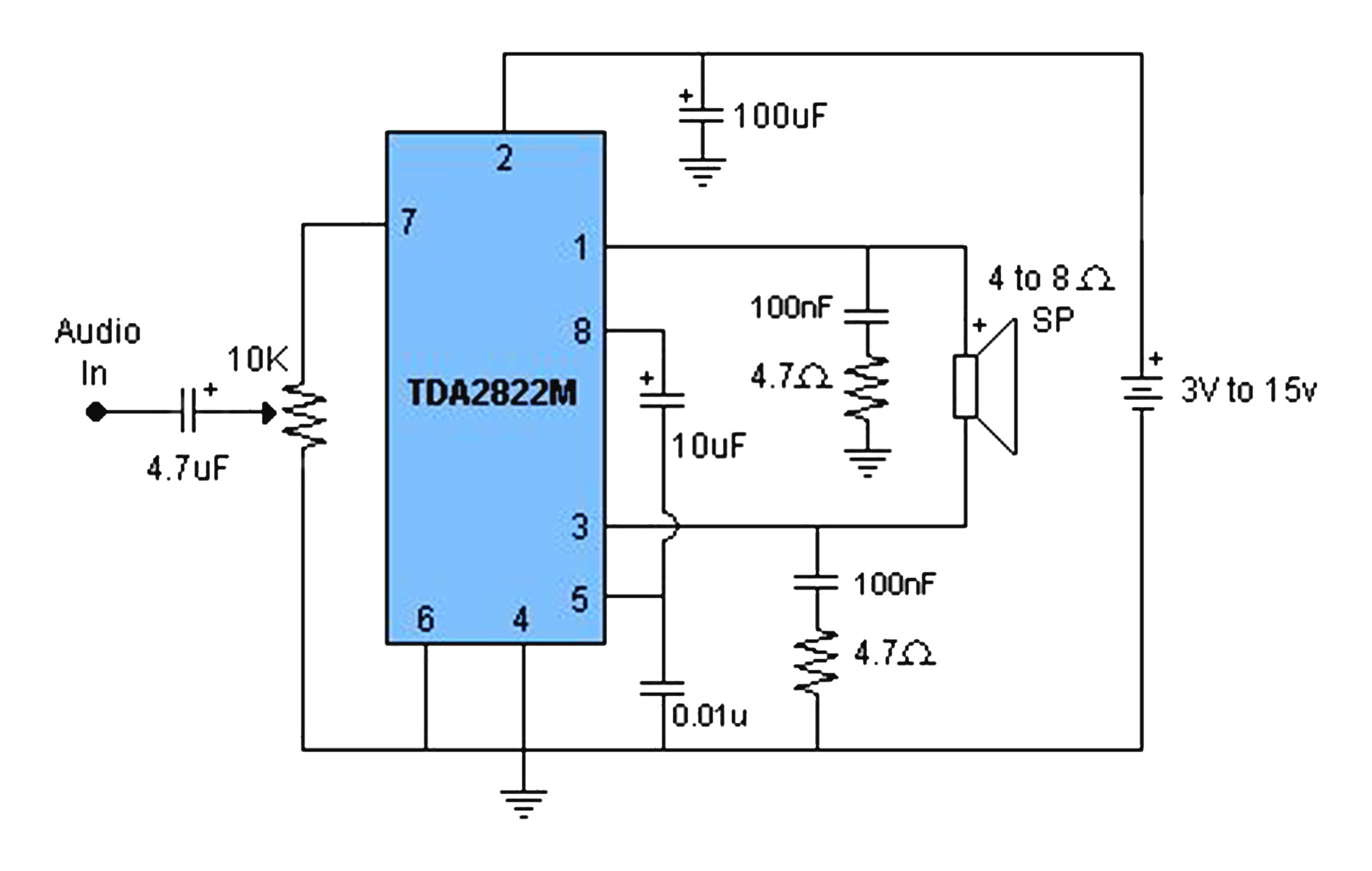
Circuit Overview:
The low power consumption of this audio amplifier makes it particularly suitable for driving small speakers, with stable performance and very low distortion.
Basic single channel amplifier of TDA2822M
The following figure shows the basic mono amplifier configuration of the TDA2822M amplifier chip.
Circuit Overview:
This simple circuit is suitable for small audio amplification projects.
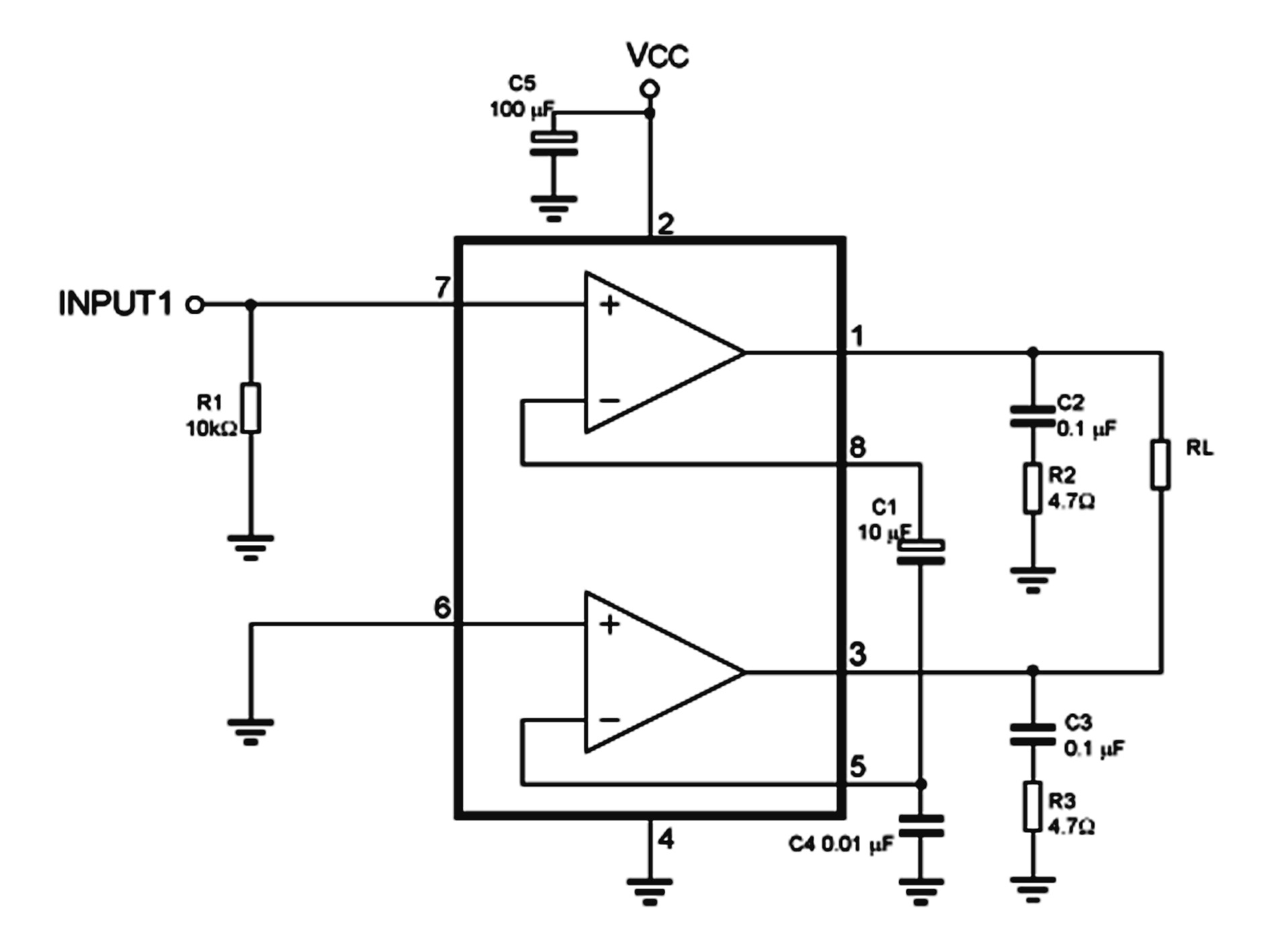
TDA2822M dual channel audio amplifier circuit
This is a two-channel (stereo) audio amplifier circuit based on the TDA2822M chip, suitable for use in portable audio devices.
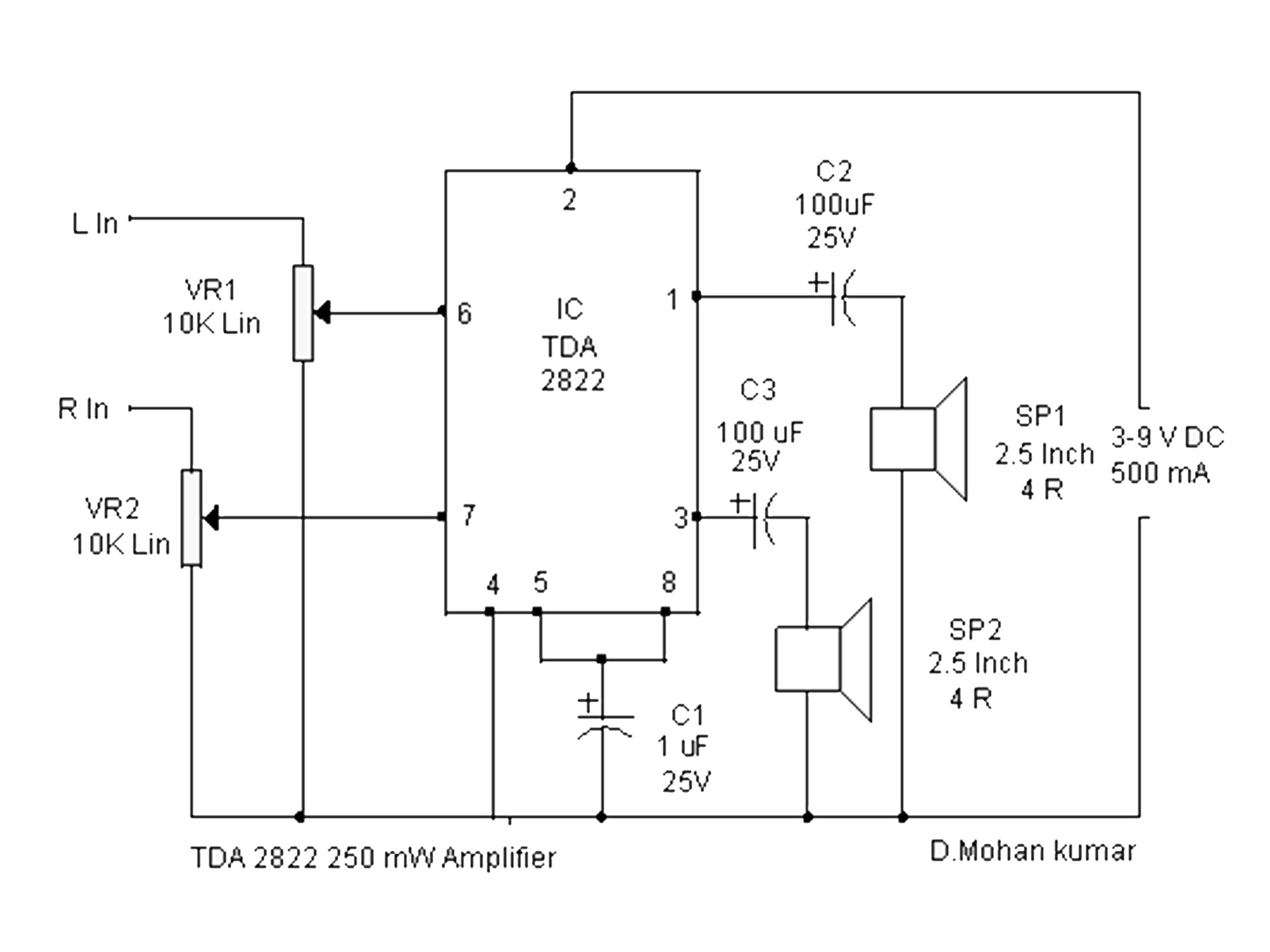
Circuit Overview:
The circuit is ideal for portable audio devices such as radios or MP3 players that amplify low-power stereo audio signals.
TDA2822M Equivalent ICs
If the TDA2822M is not readily available, you can use several equivalent ICs.These ICs provide similar functionality and can be replaced with minimal tuning in most amplifier circuits.
Exploring the TDA2822M Datasheet
The TDA2822M data book is an essential resource when building a circuit, as it provides detailed information on the IC's electrical characteristics, pin configuration, and recommended operating conditions. A data book can help you determine the correct voltage, input signal level, and power distribution for your specific application.
Key parameters from the data sheet include:
- Maximum Supply Voltage: 15V
- Typical Output Power: 1W per channel
- Static current: Typical 3mA
- Distortion: Less than 0.5% at 1W
By understanding the TDA2822M data book, you can ensure that the circuit works within safe limits and that the design is successfully implemented.
Conclusion
Building the TDA2822M audio amplifier circuit is an excellent project for anyone interested in audio electronics. Be sure to refer to the TDA2822M data book for detailed specifications and explore other equivalent circuits to extend your circuit design. With a proper understanding of the TDA2822M's structure, pins, and electrical characteristics, you can design an efficient amplifier circuit that meets your needs.
Commonly Asked Questions
What is the yield control of TDA2822M?
It gives 1W per channel at 15V, less at lower voltages.How to control a TDA2822M enhancer?
Utilize a 3V to 15V supply, commonly a 3.7V battery or 9V DC source.How to make strides TDA2822M sound quality?
Utilize legitimate capacitors for sifting, diminish twisting, and coordinate speaker impedance.What do capacitors do in a TDA2822M circuit?
They square DC, channel commotion, and stabilize the circuit.Can TDA2822M run in bridge mode?
Yes, bridge mode increments control by utilizing both channels for a single speaker.Related Information


-

-
Phone
+86 135 3401 3447 -
Whatsapp
