 Cart ( )
Understanding GND in a Circuit: A Comprehensive Guide
2024/5/21 11:56:33
Views:
Ground (GND) is a fundamental concept in electrical and electronic circuits. It serves as a reference point for voltage measurements as well as a return path for electrical current. This guide will explore the various aspects of GND, its significance, types, practical applications in circuits, and best practices for grounding. By the end of this comprehensive guide, you should have a deep understanding of GND and its crucial role in circuit design and analysis.
What is "Ground" in a Circuit?
What is GND?

In a circuit, ground, often known as GND, is a typical path for electrical current to return. It is the reference point for circuit analysis and the point against which all other voltages are measured. As a reference zero-voltage point, GND is typically linked to the earth or a sizable conducting body in practical circuits. The proper functioning of the circuit depends on the voltage at GND remaining constant and predictable, which is ensured by this connection.
The Importance of GND

1. Reference Point for Voltage Measurement:
GND provides a stable reference point for measuring voltages within a circuit. All voltage levels in the circuit are measured relative to this point. Without a common reference point, it would be difficult to determine the actual voltages at different points in the circuit.
2. Security:
Protecting against electric shocks and equipment damage can be achieved by connecting GND to the ground. By giving fault currents a safe route to safely dissipate into the soil, it lowers the possibility of electrical risks.
3. Present Return Route:
The circuit is completed by GND, which offers an electrical current return channel. A complete path is required for current to travel from the power source, through the load, and back to the source. This return path, GND, makes sure that current flows continuously.
4. Noise Reduction:
Proper grounding can help reduce electrical noise and interference, which is especially important in sensitive electronic systems. By providing a low-impedance path to the ground, noise signals can be effectively shunted away, improving the overall performance and reliability of the circuit.
Types of Ground

1. Earth Ground:
Earth ground is a physical connection to the earth, typically achieved through a metal rod or plate buried in the ground. It is used for safety and as a reference point for high-voltage systems. The earth ground provides a common reference point that is universally accepted, ensuring consistency in voltage measurements.
2. Chassis Ground:
Chassis ground refers to the connection between the circuit and the metal enclosure (chassis) of the device. It is frequently used to reduce noise and offer insulation in electrical equipment. By connecting the chassis to GND, any electrical interference picked up by the metal enclosure is directed to the ground, protecting the internal circuitry.
3. Signal Ground:
A common reference point in an electronic circuit that isn't physically connected to the earth is called signal ground. It serves as a reference for signal voltages and is often used in low-voltage and low-power applications. Signal ground aids in keeping the voltage reference steady so that the circuit can function as intended.
4. Digital Ground (DGND) and Analog Ground (AGND):
In mixed-signal circuits, which contain both analog and digital components, separate grounds are used to minimize interference. Digital ground is used for digital circuits, while analog ground is used for analog circuits. To avoid ground loops and guarantee a common reference point, these grounds are frequently joined at a single location, referred to as the star ground.
Practical Applications of GND
1. Power Supply Circuits:
In power supplies, GND serves as the return path for current from the load back to the power source. Proper grounding ensures stable and efficient operation. Power supplies often include multiple ground connections to provide a low-impedance path for return currents, reducing voltage drops and improving performance.
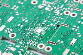
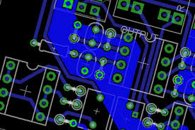
2. PCB Design:
Printed Circuit Boards (PCBs) use ground planes or traces to provide a common reference point for all components. Proper PCB grounding reduces noise, enhances signal integrity, and improves electromagnetic compatibility (EMC). Ground planes provide a large area for current return paths, minimizing impedance and reducing the risk of ground loops.
3. Communication Systems:
In communication systems, grounding is critical to prevent interference and ensure clear signal transmission. Grounding practices are essential in antenna systems, coaxial cables, and shielded cables. The quality of the signal is enhanced by the efficient dissipation of interference signals by the provision of a low-impedance link to ground.
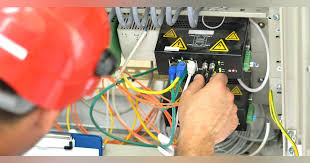
4. Industrial Equipment:
Industrial machinery and equipment use grounding for safety and operational reliability. Grounding prevents electrical shocks, protects against lightning strikes, and ensures the proper functioning of sensitive electronic controls. Large-scale grounding networks are frequently included in industrial systems to offer strong protection against electrical problems.
Grounding in Various Circuit Types

1. Analog Circuits:
Analog circuits are particularly sensitive to noise and interference. Accurate signal processing depends on proper grounding. Analog circuits often use a single point ground or star ground configuration to minimize ground loops and maintain a stable reference voltage. To further minimise interference, separate ground planes for digital and analogue circuits can be used.
2. Digital Circuits:
Digital circuits generate high-frequency signals that can cause significant noise and interference. In digital circuits, ground planes are frequently utilised to give high-frequency currents a low-impedance return path. Additionally, sensitive components are shielded from electromagnetic interference (EMI) by ground planes.
3. Mixed-Signal Circuits:
Mixed-signal circuits, which include both analog and digital components, require careful grounding to prevent interference between the two types of signals. Signal isolation and noise reduction can be achieved by connecting analogue and digital circuits' separate ground planes at a single location.
4. RF Circuits:
Radio Frequency (RF) circuits operate at high frequencies and are highly susceptible to noise and interference. Proper grounding and shielding are essential to maintain signal integrity. RF circuits often use ground planes and metal enclosures to provide effective shielding and reduce noise.
Best Practices for Grounding
1. One-point grounding
In order to prevent ground loops, which can result in interference and noise, use a single point ground connection. Voltage variations between ground points are less likely when single point grounding is used to guarantee that all ground connections reference the same potential.
2. Terrain Aircraft:
Ground planes on PCBs can be used to give return currents a low impedance channel, which lowers noise and enhances signal integrity. Ground planes minimize resistance and provide excellent shielding by offering a vast surface for current return pathways.
3. Separate Grounds for Different Signals:
In mixed-signal circuits, use separate grounds for digital and analog signals to prevent interference. Connect these grounds at a single point to maintain a common reference. This approach isolates the noisy digital signals from the sensitive analog signals, improving overall performance.
4. Proper Grounding of Equipment:
Ensure all equipment is properly grounded to the earth to protect against electrical faults and interference. Equipment that is grounded to the earth lowers the possibility of electrical risks and gives fault currents a safe route.
5. Protecting:
To lessen electromagnetic interference (EMI) and enhance signal quality, use shielded cables and enclosures. Sensitive signals and components are shielded from outside noise sources by shielding.
Advanced Grounding Techniques
1. Grounding of stars:
By joining every ground point in a circuit to a single center point, star grounding creates a configuration resembling a star. By using this method, ground loops are reduced and the same ground potential is referenced by every component. In complicated circuits, star grounding is especially useful for cutting down on noise and interference.
2. Isolation of Ground Loop:
When there are several ground routes with various potentials, it might result in ground loops, which can generate noise and undesired currents. Noise can be avoided and ground loop isolation techniques, like the use of isolation transformers or optical isolators, efficiently break the ground loop.
3. Transmission of Balanced Signals:
When a signal is transmitted using a balanced method, it is carried by two wires, one of which carries the signal and the other the inverted signal. Through the cancellation of common-mode interference, this approach lowers noise. A lot of audio and communication technologies use balanced signal transmission.
4. Capacitors for Decoupling:
Decoupling capacitors are used to regulate the power supply voltage and filter out high-frequency noise. Reducing noise and improving functionality can be achieved by decoupling capacitors next to integrated circuit (IC) power supply pins. By giving high-frequency noise a low-impedance path to ground, these capacitors effectively filter out undesired signals.
Practical Grounding Scenarios

1. Grounding in Audio Systems:
Audio systems are highly sensitive to noise and interference. Effective grounding methods, such shielding and star grounding, can greatly enhance audio quality. Grounding the audio equipment to a single point and using shielded cables can reduce hum and noise.
2. Grounding in Computer Systems:
Computer systems generate significant high-frequency noise and require effective grounding to ensure reliable operation. Ground planes in PCBs, proper chassis grounding, and the use of shielded cables can reduce noise and improve system performance. Another way to prevent electrostatic discharge (ESD) is to ground the computer chassis to the earth.
3. Grounding in Automotive Systems:
Automotive systems include a wide range of electronic components that require proper grounding for reliable operation. Grounding techniques such as star grounding, ground planes, and shielding are used to reduce noise and interference in automotive electronics. Additionally, the integrity and dependability of the car's electrical system are guaranteed by proper grounding.
4. Grounding in Industrial Control Systems:
Industrial control systems often operate in harsh environments with significant electrical noise and interference. Ground planes, shielding, and single point grounding are some examples of proper grounding techniques that can increase the dependability and efficiency of industrial control systems. Protection from lightning strikes and electrical malfunctions is another benefit of grounding the equipment to the soil.
Troubleshooting Grounding Issues

1. Identifying Ground Loops:
Ground loops
can cause significant noise and interference in a circuit. Identifying ground loops involves measuring voltage differences between ground points and looking for unexpected currents. Ground loops can be reduced with the use of a single point ground connection.
2. Using Oscilloscopes and Multimeters:
Oscilloscopes and multimeters can be used to measure voltage levels and identify grounding issues. Measuring the voltage between different ground points can reveal potential differences that indicate grounding problems.
3. Improving Ground Connections:
Poor ground connections can cause noise and interference. Ensuring solid and reliable ground connections, such as using thicker wires or multiple ground connections, can improve grounding and reduce noise.
4. Using Grounding Test Equipment:
Specialized grounding test equipment can measure the impedance of ground connections and identify potential grounding issues. Regular testing of ground connections can ensure the reliability and safety of the electrical system.
Conclusion
Understanding the concept of GND in circuits is fundamental for anyone involved in electrical and electronic engineering. In addition to ensuring safety and lowering interference and noise, grounding offers a reliable reference point for voltage measurements. By following best practices for grounding, you can design more reliable and efficient circuits, enhancing the performance of your electronic systems.
Minimizing noise and interference requires the use of proper grounding techniques, such as shielding, ground planes, and single point grounding. Advanced grounding techniques, such as star grounding and ground loop isolation, can further improve the performance of complex circuits. Whether you're working with audio systems, computer systems, automotive electronics, or industrial control systems, proper grounding is crucial for reliable and efficient operation.
By understanding the various types of ground, practical applications of grounding, and best practices for implementing effective grounding techniques, you can ensure the success of your electronic designs. Grounding is a critical aspect of circuit design and analysis, and mastering this concept will significantly enhance your ability to create high-performance and reliable electronic systems.
Related Information


-

-
Phone
+86 135 3401 3447 -
Whatsapp
