 Cart ( )
Decryption: Power supply design tips without transformer
2024/5/28 10:36:16
Views:
Transformerless Power Supply Explanation
It's not magic or a dream. Small loads can use current limiting resistors to step down 230 VAC to a few volts (like 5, 12, or 24). The efficiency is low (<1%), and R1 loses energy as heat. In reality, it takes a lot of work to step down the voltage from 230 VAC RMS to 12 VDC. This linear component dissipates 22 W on average; it must be sized to be at least 50 W, dissipating: V(N3, N2) * I(R1)
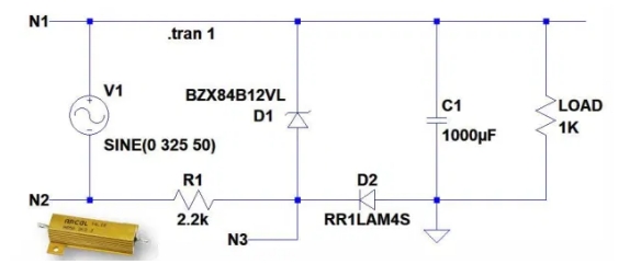
In the diagram, there are three operating nodes: N1, N2, and N3. Depending on the component values, the transient voltages are shown in the graph. The graph shows how long it takes for the output to reach 12 V depending on the time constant, also determined by capacitor C1. The charging time of the transient signal capacitor is as follows:
C1 = 100 µF, T = 25 ms
C1 = 470 µF, T = 130 ms
C1 = 1,000 µF, T = 290 ms
C1 = 4,700 µF, T = 1.38 s
C1 = 10,000 µF, T = 3 s
At a fixed load resistance, the ripple depends on the capacitor C1. The larger the capacitor, the less ripple appears on the output signal. Using the above capacitors, the peak-to-peak ripple amounts are as follows:
• C1 = 100 µF, Ripple = 1.17 Vpp
• C1 = 470 µF, Ripple = 261.7 mVpp
• C1 = 1,000 µF, Ripple = 121.58 mVpp
• C1 = 4,700 µF, Ripple = 25.3 mVpp
• C1 = 10,000 µF, Ripple = 11.89 mVpp
The output voltage of the circuit does not reach the required 12 V, but is about 11.3 V. Even when no load is connected, the output voltage is always below 12 V. This voltage drop is caused by diode D2. The Schottky diode reduces this voltage drop.
2. Capacitor Improvement
From the graph, it can be seen that adding a polyester capacitor in series with the line improves the system efficiency. In this configuration, the efficiency is about 18%.
Since the maximum voltage across the capacitor is greater than 320 V, a model supporting at least 650 V must be selected.
With this configuration, resistor R1 dissipates only 0.5 W, but it is better to use a model of at least 2 W. Capacitor C2 acts as a resistor and has a capacitive reactance at a frequency of 50 Hz. The capacitive reactance of a capacitor is expressed by the following formula:
From this it follows that the reactance of capacitor C2 is 6772.55 Ω, but unlike a resistor, it does not dissipate heat. The output voltage of the circuit is also 12 V, from which the voltage drop of diode D1 must be subtracted.
Caution: Capacitor C2 may stay charged for a considerable amount of time when the circuit is closed. It is recommended to connect a high-ohmic resistor in parallel with this component. In typical operation, it dissipates approximately 100 milliwatts. Complete discharge of the capacitor takes about 1 second, but after 0.4 seconds, its voltage value is no longer dangerous.
It's not magic or a dream. Small loads can use current limiting resistors to step down 230 VAC to a few volts (like 5, 12, or 24). The efficiency is low (<1%), and R1 loses energy as heat. In reality, it takes a lot of work to step down the voltage from 230 VAC RMS to 12 VDC. This linear component dissipates 22 W on average; it must be sized to be at least 50 W, dissipating: V(N3, N2) * I(R1)
In the diagram, there are three operating nodes: N1, N2, and N3. Depending on the component values, the transient voltages are shown in the graph. The graph shows how long it takes for the output to reach 12 V depending on the time constant, also determined by capacitor C1. The charging time of the transient signal capacitor is as follows:
C1 = 100 µF, T = 25 ms
C1 = 470 µF, T = 130 ms
C1 = 1,000 µF, T = 290 ms
C1 = 4,700 µF, T = 1.38 s
C1 = 10,000 µF, T = 3 s
At a fixed load resistance, the ripple depends on the capacitor C1. The larger the capacitor, the less ripple appears on the output signal. Using the above capacitors, the peak-to-peak ripple amounts are as follows:
• C1 = 100 µF, Ripple = 1.17 Vpp
• C1 = 470 µF, Ripple = 261.7 mVpp
• C1 = 1,000 µF, Ripple = 121.58 mVpp
• C1 = 4,700 µF, Ripple = 25.3 mVpp
• C1 = 10,000 µF, Ripple = 11.89 mVpp
The output voltage of the circuit does not reach the required 12 V, but is about 11.3 V. Even when no load is connected, the output voltage is always below 12 V. This voltage drop is caused by diode D2. The Schottky diode reduces this voltage drop.
2. Capacitor Improvement
From the graph, it can be seen that adding a polyester capacitor in series with the line improves the system efficiency. In this configuration, the efficiency is about 18%.
Since the maximum voltage across the capacitor is greater than 320 V, a model supporting at least 650 V must be selected.
With this configuration, resistor R1 dissipates only 0.5 W, but it is better to use a model of at least 2 W. Capacitor C2 acts as a resistor and has a capacitive reactance at a frequency of 50 Hz. The capacitive reactance of a capacitor is expressed by the following formula:
From this it follows that the reactance of capacitor C2 is 6772.55 Ω, but unlike a resistor, it does not dissipate heat. The output voltage of the circuit is also 12 V, from which the voltage drop of diode D1 must be subtracted.
Caution: Capacitor C2 may stay charged for a considerable amount of time when the circuit is closed. It is recommended to connect a high-ohmic resistor in parallel with this component. In typical operation, it dissipates approximately 100 milliwatts. Complete discharge of the capacitor takes about 1 second, but after 0.4 seconds, its voltage value is no longer dangerous.
Related Information


-

-
Phone
+86 135 3401 3447 -
Whatsapp
