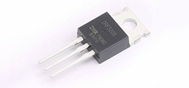
Preventing power MOS tube failure: Preventive measures for voltage and current
2024/1/17 14:54:18
Views:
MOS tubes are susceptible to various faults in practical applications, including overvoltage (semiconductor avalanche breakdown), overcurrent (bonding wire or substrate melting), overheating (semiconductor material decomposition due to high temperature), etc.
Overvoltage problem
MOS tubes have very limited tolerance for overvoltage, and even exceeding the rated voltage for just a few nanoseconds may cause equipment damage. Therefore, in circuit design, special attention must be paid to suppressing any voltage spikes or ringing to ensure that the rated voltage of the MOS tube is within a safe range.
Overload problem
Power overload is another common cause of MOS tube failure. When the current exceeds the absolute maximum rating and there is insufficient heat dissipation, the MOS tube is easily damaged. To prevent this, engineers must consider appropriate thermal solutions and ensure that the current flow remains within safe limits.
Breakdown and cross-conduction issues
A breakdown condition may occur when the control signals of two opposing MOS transistors overlap, which will cause both MOS transistors to conduct at the same time, thus short-circuiting the power supply. In order to prevent this situation, the switching transition between the two MOS tubes can be limited by introducing dead time to ensure that one MOS tube turns off before the other MOS tube turns off.
Freewheeling current path problem
When switching current through any inductive load, a back EMF is generated when the current is turned off. This can cause problems if neither switchgear provides a freewheeling path. Normally, freewheeling current is safely directed back to the supply rail through freewheeling diodes connected in antiparallel to each switching device.
The problem of slow reverse recovery of MOS transistor body diodes
In some cases, a high-Q resonant circuit may cause current to continue through the internal body diode of the MOSFET, and the slow reverse recovery of the internal body diode may cause problems when another MOSFET attempts to turn on. In order to solve this problem, a diode can be added to alleviate it and ensure that the freewheeling current does not drive the MOS body diode to conduct.
Gate drive issues
If too high a voltage is used to drive the gate of a MOS tube, the gate oxide layer may be damaged, causing the MOS tube to fail to work properly. Therefore, it is necessary to ensure that the gate drive signal does not produce narrow voltage spikes that may exceed the maximum allowed gate voltage.
Insufficient gate drive problem
In order to minimize the power consumption during the conduction period of the MOS tube, it is necessary to ensure that the MOS tube is fully turned on. If the MOS tube is not fully turned on, the device will have high resistance and consume a lot of power in the form of heat. Maintaining a gate voltage between 10 and 15 volts ensures that most MOS tubes are fully turned on.
Switching speed problem
During the on and off states, the MOS tube produces almost no energy loss, but during the transition period, a large amount of energy is consumed. Therefore, switching between states should be done as quickly as possible to minimize power consumption during switching.
Spurious oscillation problem
The high current switching capabilities and relatively high input impedance of MOS tubes may cause stability problems. In some cases, high-voltage MOS tubes may oscillate at very high frequencies, which is undesirable because it causes high dissipation. To prevent this, stray inductance and capacitance around the MOS tube must be minimized, and a low-impedance gate drive circuit must be used to prevent stray signals from coupling to the gate of the device.
Miller effect problem
MOS tubes have a large Miller capacitance between the gate and drain, which may cause problems in high-voltage fast switching applications. To solve this problem, a low impedance gate driver can be used to minimize the Miller effect, thereby reducing the impact of any spikes from the drain on the gate.
Radiation interference problems to the controller
Good isolation and shielding of the controller and power supply are key to preventing radiated interference. High-impedance points in control circuits may cause abnormal operation, so it is important to ensure that control electronics are effectively shielded.
Conducted interference issues on the controller
Rapid switching of large currents can cause voltage sags and transient spikes on the power rails, causing disturbances in the control circuitry. In order to reduce the impact of conducted interference, appropriate decoupling is required
and neutral point grounding techniques. It is very effective to use transformer coupling to drive MOS tubes, which can prevent electrical noise from being conducted back to the controller.
Static electricity damage problem
When installing MOS tubes or IGBT devices, anti-static measures must be taken to prevent damage to the gate oxide layer.
High standing wave ratio problem
In pulsed systems, the VSWR problem is not as significant as in CW systems, but it is still worthy of attention. Reflected power can cause a variety of problems, including overloading equipment with rated power consumption and standing waves in lines. Therefore, matching issues must be considered in the design to minimize the impact of reflected power.
These are some common causes and solutions for MOS tube burnout. To ensure the stable operation of the MOS tube, attention must be paid to circuit design, heat dissipation, gate drive, reverse recovery, freewheeling path and other issues. At the same time, preventing electrostatic damage and reducing standing wave ratio are also key factors. Taking these factors into consideration can effectively reduce the risk of MOS tube failure and improve the reliability of the system.
Related Information
-
-
Phone
+86 135 3401 3447 -
Whatsapp


