Understanding Pins: The Key to Connecting Electronic Components
2024/2/19 10:40:46
Views:
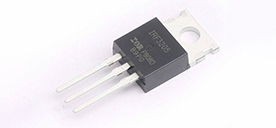
Pins refer to the lead-out ports on electronic components or integrated circuit chips, used to connect external circuits or other components. Generally, the pins of integrated circuit chips are connected to the internal pins of the chip through packaging technology, thereby enabling interaction with the external world.
Common types of pins
1. Input pin
Input Pin: used to receive signals or data from external circuits or other components.
2. Output pin
Output Pin: Used to send signals or data to external circuits or other components.
3. Power pin
Power Supply Pin: used to provide the power supply voltage and current required by the chip or component.
4. Ground pin
Ground Pin: Used to provide a reference ground or current return path for the loop.
5. Clock pin
Clock Pin: used to provide clock signals for synchronous operation or timing control.
6. Reset pin
Reset Pin: Used to restore the chip or component to its initial state.
Pin type
1. Output pin
Output pins are used to send signals or data from the chip or component to external circuits or other components. Output pins can provide analog or digital signals for use by other devices. For example, the output pins of an LED driver chip can be connected to an LED light in order to control its brightness and blinking effect.
Output pins can also be used to control various external devices such as motors, displays, audio equipment, etc. They play a key role in electronic systems, ensuring that the chip or component interacts correctly with the outside world and provides the required functionality.
2. Ground pin
The Ground Pin is the pin connected to the reference ground or current return path of the loop. It provides a stable potential reference point to ensure the accuracy and stability of signal transmission. The ground pin is usually connected to the power pin, forming a closed circuit loop to ensure that current can flow smoothly from the chip or component back to the power supply to maintain stable operation of the circuit.
In complex electronic systems, there may be multiple ground pins to better manage and separate different current loops. Proper connection and layout of ground pins is important to reduce interference, eliminate noise, and improve overall system reliability.
3. Clock pin
The clock pin (Clock Pin) is used to provide clock signals for synchronous operation and timing control. Clock signals determine the timing relationships and sequence of operations between components within an electronic system. With an externally provided clock signal, chips or components can perform precise timing and coordination.
The clock pin is usually connected to a crystal oscillator or other clock source to ensure that various operations within the system occur at the correct time intervals. The frequency and stability of the clock signal are critical to system performance and accuracy.
4. Power pin
Power pins are the supply voltage and current pins connected to the chip or component. They provide the necessary electrical energy to the chip or component to ensure its normal operation. The power pin is usually divided into two pins: positive (Vcc) and negative (GND). The positive terminal provides positive voltage and the negative terminal is used as ground.
Depending on the specific chip or component specifications, the power pins may require specific voltage and current levels. When designing electronic circuits, it is crucial to properly connect and power the power supply pins to ensure that the chip or component is functioning properly.
5. Reset pin
The Reset Pin is used to restore the chip or component to its initial state. When the reset pin receives a signal of a specific level, the chip or component will restart or clear its internal state. The reset pin is typically connected to a reset button, switch, or other controller so that the user can restart the device or clear an error state by triggering a reset signal.
Reset pin plays an important role in electronic systems, especially in embedded systems and microcontrollers. By using the reset pin correctly, you can ensure that the system can reliably recover and restart in the event of a fault or abnormal situation.
Understanding these common pin types is critical to properly designing and wiring electronic circuits. Accurately understanding the function and purpose of each pin can help engineers design more reliable, stable, and high-performance electronic systems. Through in-depth research and continuous learning, we can better utilize and unleash the potential of pins and promote the development and innovation of electronic technology.
Related Information
-
-
Phone
+86 135 3401 3447 -
Whatsapp


