What is an operational amplifier? characteristics, circuit and application
2024/11/19 12:30:32
Views:
Operational amplifier (Op-Amp) is a very important component in electronics, which is widely used in various analog circuits. They are used almost everywhere from audio amplification to signal conditioning. If you are interested in electronic circuit design, it is very important to know the basics of operational amplifiers.
This article will detail the definition of op-amp, working principle, common circuit types, practical applications and how to choose the right op-amp to help you better understand this important electronic component.
What is an operational amplifier?
Table of Contents
- what is operational amplifier?
- operational amplifier symbol
- how does operational amplifier work
- operational amplifier parameters and characteristics
- operational amplifier types
- Operational amplifier circuit
- operational amplifier applications
- how to choose an operational amplifier?
- Conclusion
- Frequently Asked Questions
1. What is operational amplifier?
Operational amplifier (Op-Amp) is a kind of electronic amplifier with high gain. It can amplify weak electrical signals and is widely used in analog signal processing. Its input signal is output after amplification, and usually has a very high input impedance and low output impedance. The operational amplifier stabilizes the gain through negative feedback for accurate signal processing.
Operational amplifiers were first invented by electrical engineers in the 1950s to perform various mathematical operations (such as addition, subtraction, multiplication, and so on), which is where the name "operation" comes from. Nowadays, operational amplifiers are no longer only used for mathematical calculations, but are widely used in audio processing, sensor signal amplification, filter design, and many other fields.
2. Operational amplifier symbol
In circuit design, there is a standardized circuit symbol to represent the computational amplifier (Op-Amp), usually consisting of a triangle representing the main function of the amplifier, with two inputs (positive input and negative input) and an output terminal. This symbol is a common and important element in electronic circuits and is used to illustrate how operational amplifiers are connected and work.
2.1 Components:
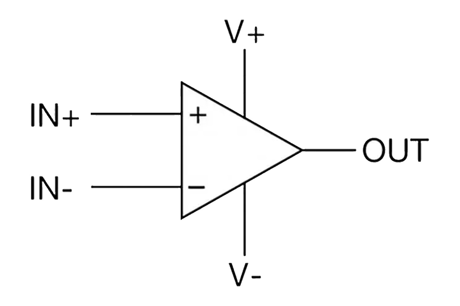
Triangle: represents the core part of the operational amplifier.
Two inputs: one for positive input (+) and one for negative input (-).
Output terminal: Used to output the amplified signal.
Power: Operational amplifiers usually require positive and negative power supplies (+Vcc and -Vcc).
3. How does operational amplifier work
The operating principle of operational amplifiers is based on the "amplification" effect of current. It produces an output signal by comparing the input signal with an internally assigned reference signal. The key point is that it uses a negative feedback mechanism to control the gain, so that the relationship between the output signal and the input signal is stable.
Input: The op-amp has two inputs -an inverting input (-) and an in-phase input (+). Signal input is passed through these two ports separately.
Gain: The core function of an operational amplifier is to amplify the input signal, usually with a very high gain (up to several million times).
Output: There is a strong relationship between the output signal and the input signal of the operational amplifier. The output voltage is the product of the input signal difference and gain.
Feedback mechanisms: In order to control gain and stability, feedback mechanisms are often used in operational amplifiers. The amplifier is adjusted to maintain stable operation by feeding back a part of the output signal to the input.
4. Operational amplifier parameters and characteristics
5. Operational amplifier types
Operational amplifiers are versatile electronic components that are widely used in scenarios such as signal amplification, filtering, integration, and differentiation. According to different design requirements and application scenarios, operational amplifiers can be divided into the following types:
5.1 Low noise operational amplifier:
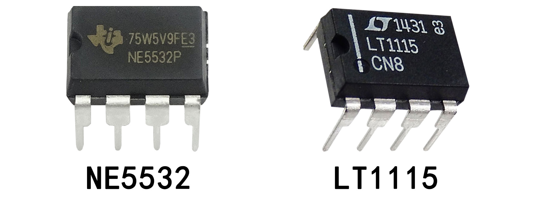
Designed to minimize built-in noise and ensure clear amplification of weak signals. Common models such as NE5532 and LT1115, which usually have low input noise voltage.
5.2 Precision operational amplifier:
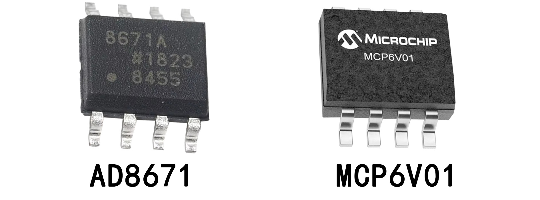
Ultra-low input bias voltage and low temperature drift provide high accuracy signal amplification. They are stable and have little temperature effect. Common models such as the AD8671 and MCP6V01, this type of amplifier pays special attention to accuracy and stability.
5.3 High speed operational amplifier:
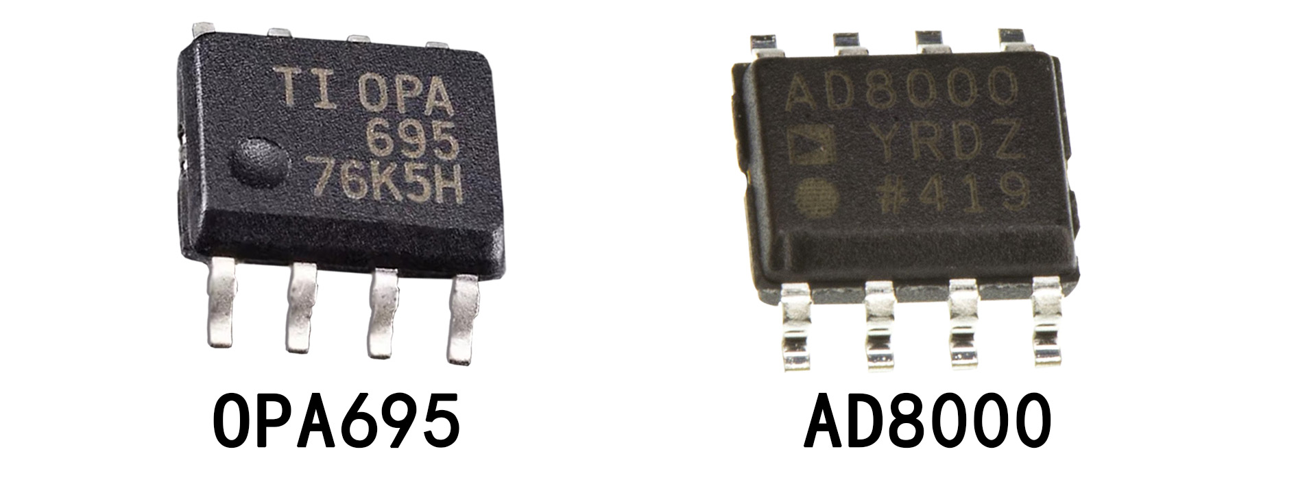
The most important features are the high gain-bandwidth product and fast response capability, which makes it have extremely high performance when processing high-speed signals. Common models such as OPA695 and AD8000, which have low propagation delay, are able to maintain excellent stability and low delay in high-frequency signals.
5.4 Low power operational amplifier:
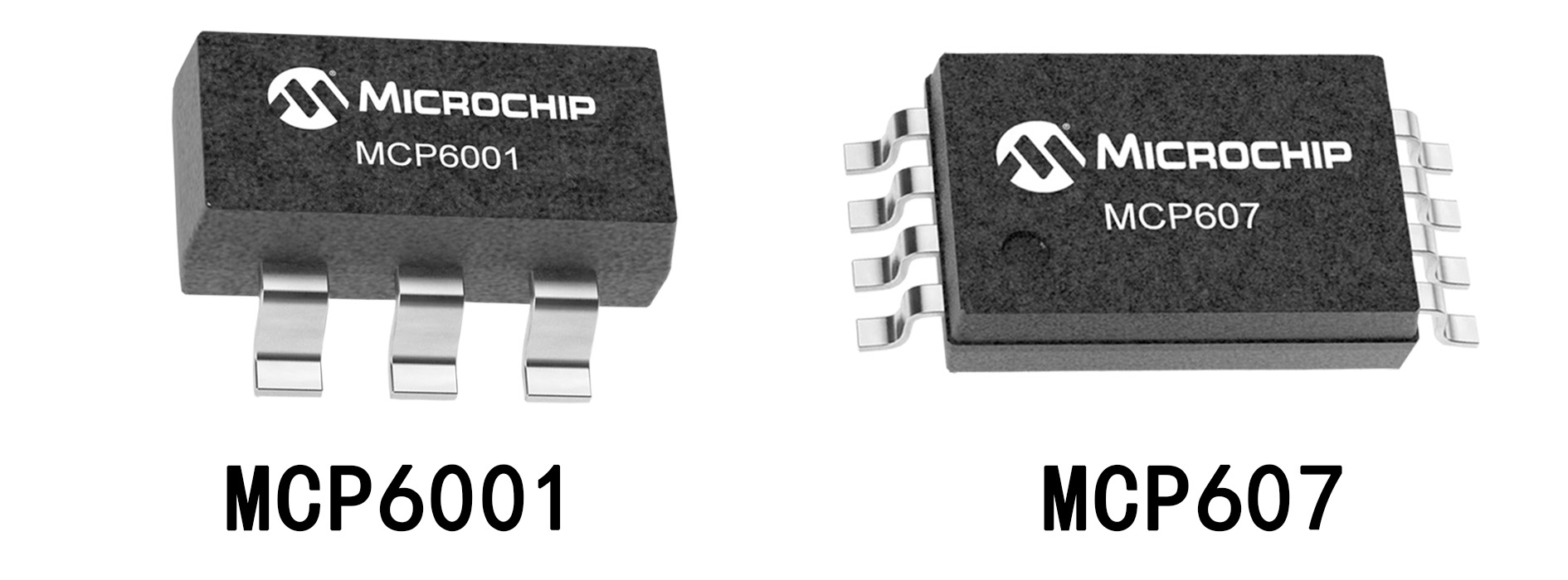
The energy consumption is optimized while ensuring performance, which is very suitable for battery-powered devices. These amplifiers are designed to have low quiescent current and are able to operate at low voltage, extending battery life. Common models such as MCP6001 and MCP607 are capable of operating at low voltages.
5.5 Rail to rail operational amplifier:
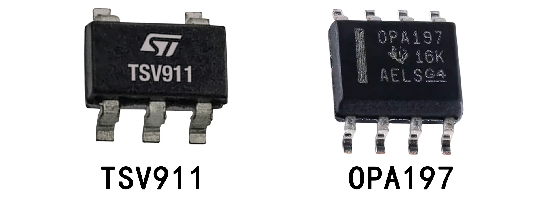
The outstanding feature is the ability to make the input and output signals close to the voltage of the power rail, greatly extending the operating voltage range. Common models, such as TSV911 and OPA197, operate at very low supply voltages and provide efficient signal amplification.
5.6 Current feedback operational amplifier:
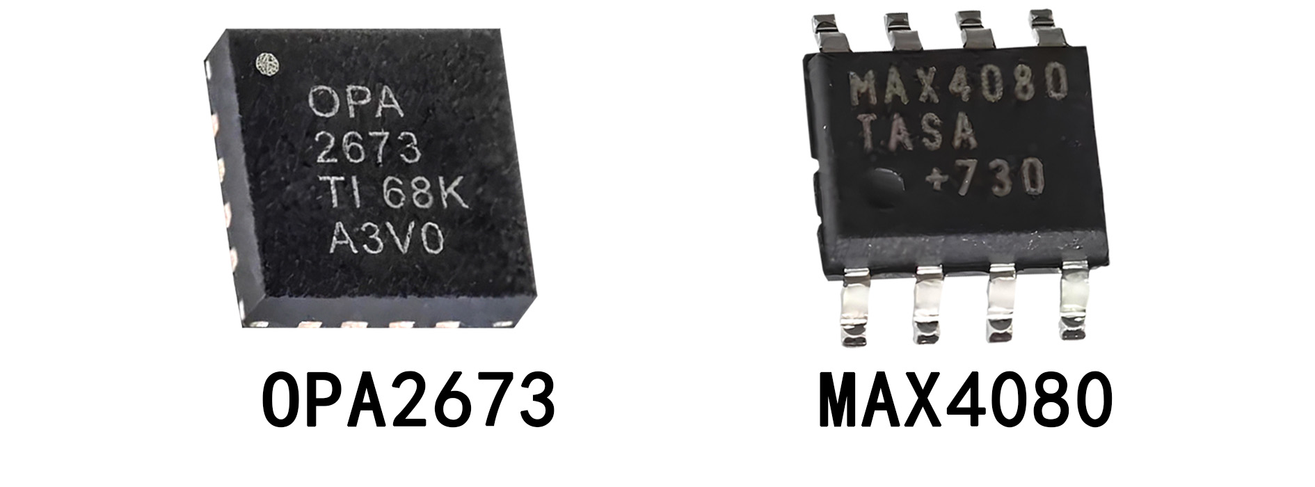
The current-feedback operational amplifier is different from the conventional voltage-feedback amplifier in that it modulates the gain by feedback current, providing a higher gain-bandwidth product and faster response. Common models such as OPA2673 and MAX4080, their core features are high gain bandwidth product and fast response.
5.7 Differential operational amplifier:
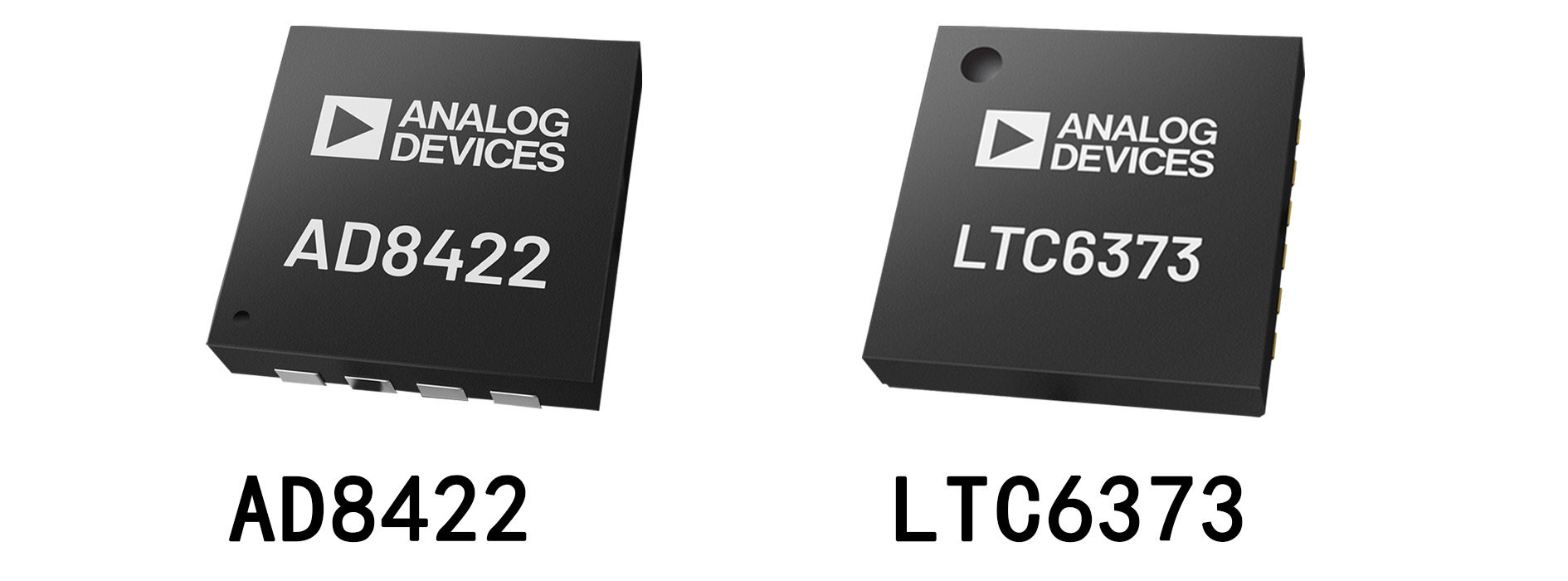
Focusing on amplifying the difference of two input signals and suppressing common-mode signal interference, it is especially suitable for accurate voltage and current differential amplification. Common models, such as AD8422 and LTC6373, can effectively filter out common-mode noise and maintain signal accuracy.
6. Operational amplifier circuit
A typical operational amplifier circuit diagram consists of two inputs, inverting and non-inverting, and one output. The diagram may also include resistors, capacitors, and feedback elements to control the gain and performance of the circuit. Here are some common examples of op-amp circuits:
6.1 Non-inverting amplifier circuit
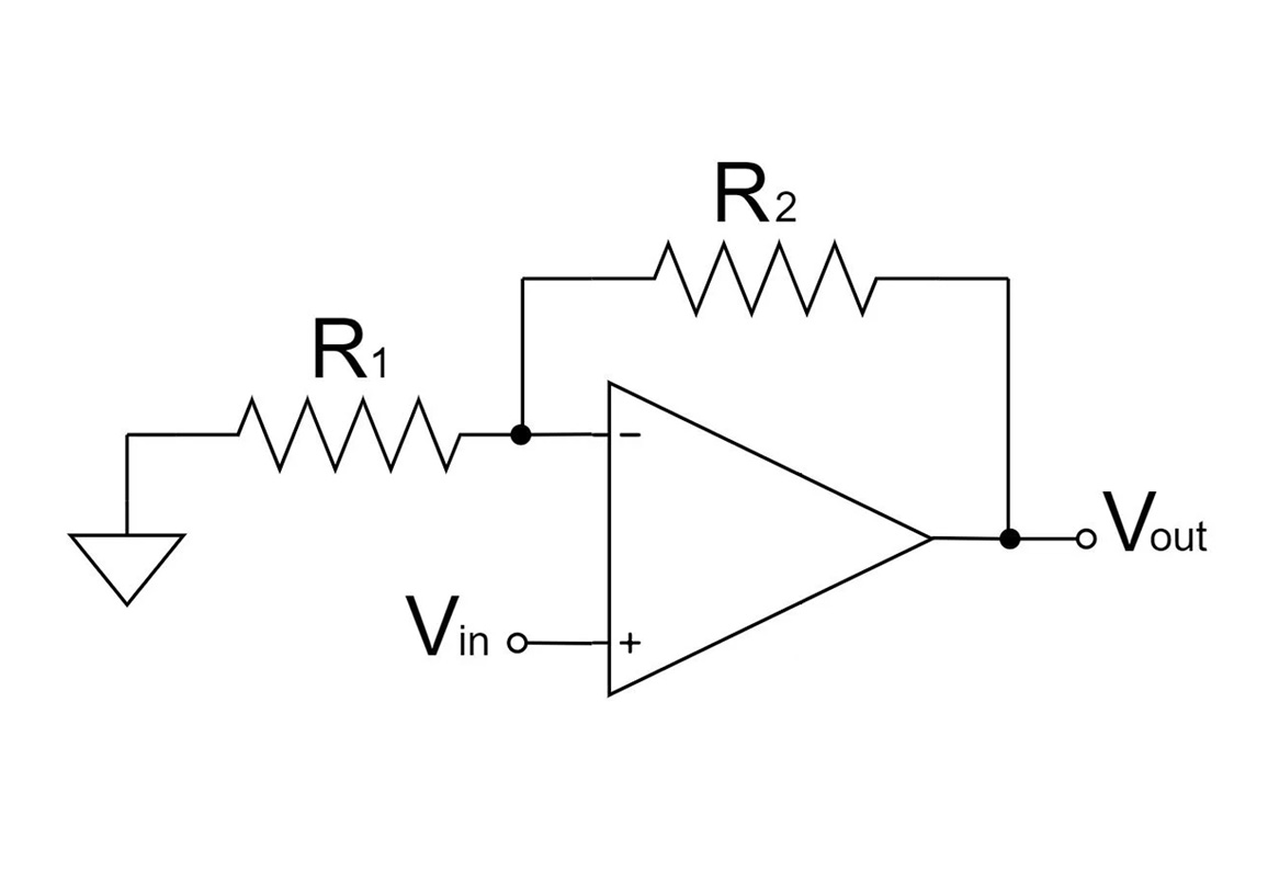
This is a circuit diagram of a non-inverting amplifier, which is widely used in signal amplification circuits.
Circuit Composition:
Input signal (Vin) : connected to the positive input of the op-amp (+).
Feedback networks (R1 and R2) : R1 is grounded, and R2 connects the output to the negative input (-) to form negative feedback. The magnification is determined by the resistance: Au=1+R2/R1.
Output signal (Vout) : in phase with the input signal (not reversed).
Working principle: The input signal directly affects the output through the positive input, the negative feedback network ensures stable amplification, and the output signal is in phase with the input signal.
6.2 Bandpass filter circuit
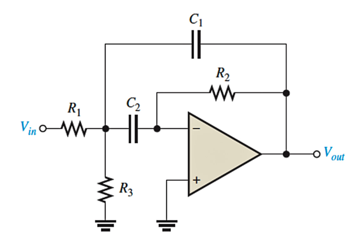
This is a bandpass filter circuit consisting of an operational amplifier and some passive components (resistors and capacitors).
Circuit Composition:
Input signal (Vin): It enters the circuit through resistor R1 and capacitor C2.
Negative feedback network: including R2 and C1, used to regulate the gain and filtering characteristics.
Ground resistance (R3): Provides a stable reference potential.
Output signal (Vout): Output after filtering.
Working principle: The circuit can amplify the signal in a certain frequency range while suppressing the low frequency and high frequency signals beyond the range. The values of R and C determine the center frequency and bandwidth of the filter.
6.3 Differential amplifier circuit
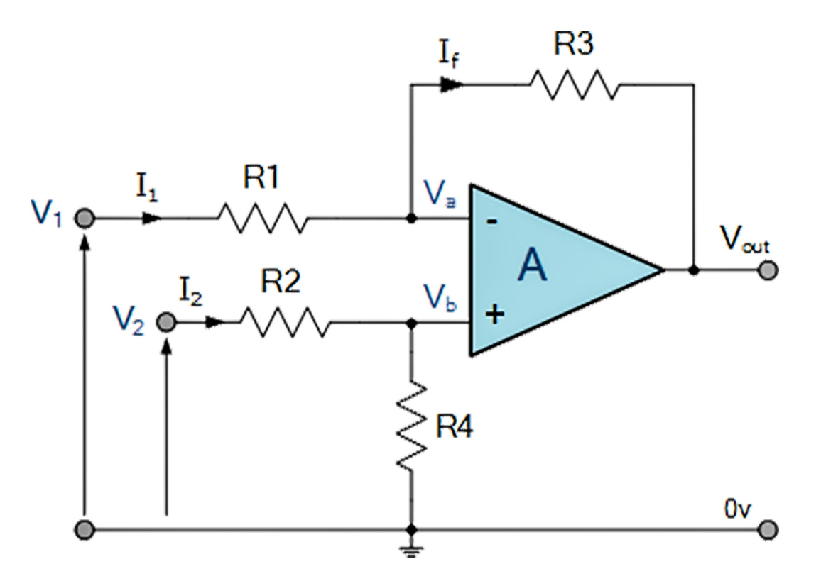
This is a differential amplifier circuit showing a circuit with two input voltages V1 and V2. Its main function is to amplify the difference between two input signals V1 and V2, while suppressing their common pattern signal.
Circuit Composition:
Input resistors R1 R2: connect the two input signals И and to the inverting input of the operational amplifier, respectively. R1 and R2 determine the weighting ratio of the input signal.
Feedback resistor R3: connects the output Vout to the inverting input and is used to control the gain of the amplifier.
Ground connection: THE non-inverting INPUT ("+") is grounded to ensure that the op-amp operates in inverting amplifier mode.
Output Vout: is the amplified output of the weighted sum (or sum) of V1 and V2.
Its main function is to amplify the difference between two input signals V1 and V2, while suppressing their common pattern signal.
6.4 Audio amplifier circuit
.jpg)
This is an audio amplifier circuit used to amplify the input audio signal. The core is the operational amplifier (GS4558), which sets the gain and frequency response through the feedback network.
Circuit Composition:
The input part: C2 (22µF) blocks the DC component of the input signal, R2 (10kΩ) stabilizes the input signal, 3 (3.3kΩ) and C5 (1000pF) suppress high-frequency interference.
Feedback network: R1 (20kΩ) and C1 (150pF) determine the gain and frequency response of the circuit, and R4 (6.8kΩ) sets the bias and affects the gain.
Power bypass capacitors: C3 and C6 (0.1µF) are used to filter out power noise and ensure stable operation of the op-amp.
Output part: C4 (22µF) : used to block the DC component of the output signal, R5 (10kΩ) : provides the load impedance.
Working principle: The input signal enters the op-amp after direct isolation and current limiting processing, and the feedback network controls the amplification factor, and finally outputs the amplified signal without DC offset. It is often used in audio signal processing and low power audio amplifier.
7. Operational amplifier applications
Operational amplifiers are widely used in many fields, such as audio processing, signal adjustment, control system and so on. Here are some common operational amplifier applications:
7.1 Signal amplification:
Operational amplifiers are used in audio amplifiers, instrument amplifiers, etc., to amplify weak signals to a level suitable for processing and transmission, and are widely used in audio, medical, and measurement equipment.
7.2 Filter design:
Combined with resistors and capacitors, operational amplifiers can be used to design low-pass, high-pass, band-pass and band-stop filters to remove unwanted frequency components for application in signal processing and communication systems.
7.3 Oscillator:
Operational amplifiers can generate stable periodic signals, such as sine wave, square wave and triangle wave, which are used in clock generators, frequency synthesizers and other occasions.
7.4 Differential amplifier:
Differential amplifier can amplify the difference of two input signals and suppress the common mode signal, which is widely used in sensor signal amplification and precision measurement.
7.5 Comparator:
Operational amplifiers are used as comparators to compare the size of input signals and are widely used in analog to digital conversion, overvoltage protection and signal threshold detection.
7.6 Adder and subtractor:
Operational amplifiers can be used as adders or subtractors to perform signal addition or subtraction operations, and are commonly used in signal synthesis, differential measurements, and mixed-signal processing.
7.7 Integrators and differentiators:
Operational amplifiers can be configured as integrators and differentiators for integration and differentiation of signals, which are widely used in dynamic system analysis and PID control.
7.8 Voltage follower:
The voltage follower provides low output impedance to ensure stable signal transmission and is widely used for signal isolation and impedance matching.
7.9 Negative feedback control system:
Operational amplifiers are widely used in automatic control and precision instruments to ensure the stability of the control system by adjusting the gain and system response through negative feedback.
8. How to choose an operational amplifier?
When choosing an op-amp, you need to consider several factors to ensure that it is right for your specific application needs. Here are some selection criteria:
8.1 Gain-bandwidth product:
There is a trade-off between gain and bandwidth for different op-amps. For applications that require high gains, you may want to choose an op-amp with a narrower bandwidth and vice versa.
8.2 Input impedance and output impedance:
High input impedance and low output impedance are desirable op-amp characteristics. Depending on your circuit requirements, choose an operational amplifier with appropriate impedance matching.
8.3 Noise characteristics:
If your application is sensitive to noise (such as audio amplification applications), you will want to choose a low noise operational amplifier.
8.4 Price and Availability:
Different types of operational amplifiers vary greatly in price. According to your budget and needs, choose the most cost-effective operational amplifier.
9. Conclusion
Operational amplifier is a very important electronic component. It not only plays an important role in academic research, but also is widely used in industry, communication, audio and medical fields. By understanding the operational principles, characteristics, applications, and selection criteria of op-amps, you can better design and optimize various circuits.
If you want to learn more about op-AMP, you can check out the op-AMP datasets, PDFS, and circuit diagram examples that will help you gain a deeper understanding of this important component.
10. Frequently Asked Questions
1. what are the characteristics of an ideal operational amplifier?
It has infinite gain, bandwidth, and input impedance, with zero output impedance and perfect linearity.2. what is ideal operational amplifier?
An ideal op-amp is a theoretical amplifier with no noise, infinite precision, and no physical limitations.3. what is operational transconductance amplifier?
An OTA converts input voltage into output current and is used in filters, oscillators, and amplifiers.4. how to solve op amp circuits?
Use ideal op-amp rules, set up equations based on the circuit, and solve while ensuring no saturation.Related Information
-
-
Phone
+86 135 3401 3447 -
Whatsapp

