 Cart ( )
How to Build an LM386 Amplifier: Best LM386 Circuit Design
2024/10/16 18:22:08
Views:
The LM386 may be a well known low voltage control intensifier utilized in a assortment of audio applications due to its simplicity, affordability, and flexibility. In this article, we are going take a brief see at the LM386 speaker.
LM386 Amplifier. Loud, cheap and reliable.
Table of Contents
- Overview of the LM386 Amplifier
- LM386 Pinout and Functions
- Designing an LM386 Amplifier Circuit
- LM386 package diagram
- lm386 datasheet
- Summary
- Commonly Asked Questions
Overview of the LM386 Amplifier
The LM386 chip is an coordinates low-voltage sound control intensifier basically planned for battery-powered devices. It is well-suited for convenient radiosand other audio-based applications where low control utilization is pivotal. One of the key reasons for its far reaching utilize is its negligible external component requirement, permitting you to construct a utilitarian enhancer circuit with fair a couple of inactive components.
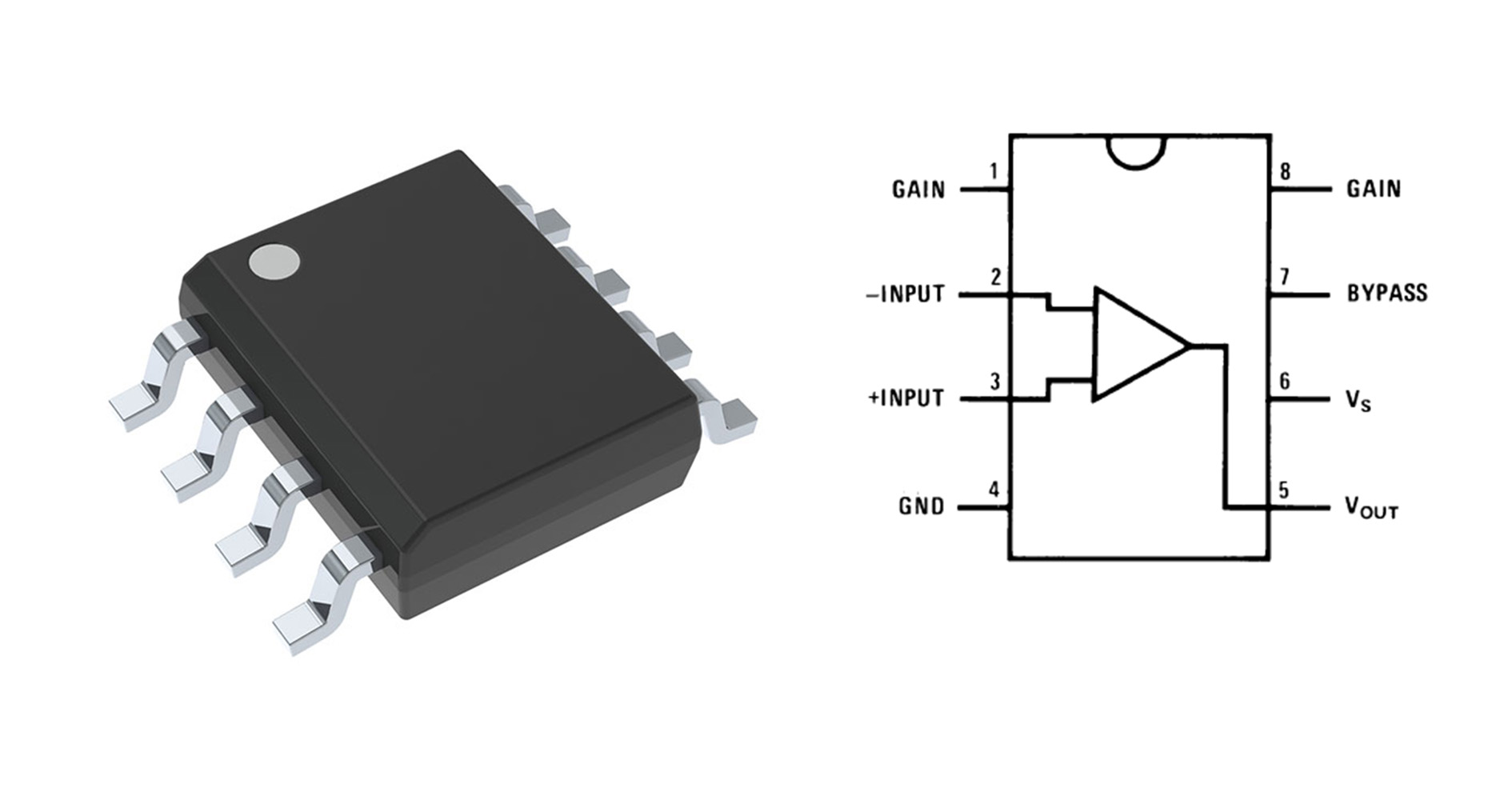
LM386 Pinout and Functions
To completely get it how to coordinated the LM386 into your ventures, it is basic to get a handle on the LM386 pinout and its related capacities.
LM386 Pin
Designing an LM386 Amplifier Circuit
lm386 audio amplifier
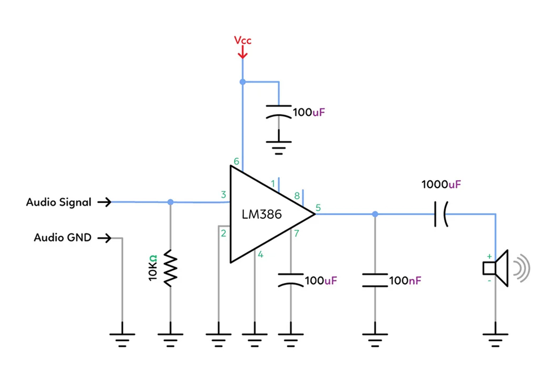
Usually an audio amplifier circuit utilizing the LM386 IC. It takes an sound flag input, intensifies it, and drives a speaker. The circuit incorporates capacitors for sifting and soundness, with a 10kΩ resistor to control the pick up. The LM386 opens up the input flag, and the yield is sent to the speaker through a capacitor, guaranteeing smooth sound enhancement. It works with a Vcc control supply and employments capacitors (100μF, 1000μF, and 100nF) to channel commotion and stabilize the circuit.
Power amplifier circuit on LM386
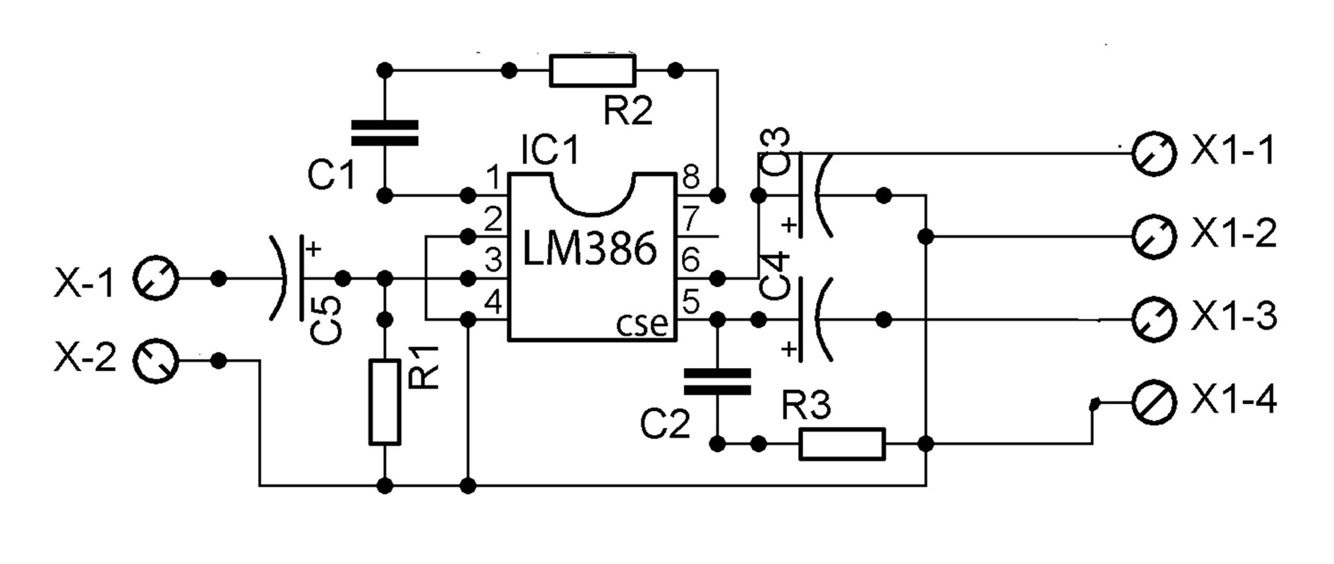
Usually a power amplifier circuit based on the LM386 IC. It opens up an input flag (X1-1 and X1-2) and yields it to numerous terminals (X1-3 and X1-4). The circuit incorporates capacitors (C1, C2, C4, C5) for sifting and solidness, and resistors (R1, R2, R3) for setting pick up and controlling the flag. This sort of circuit is commonly utilized for low-power audio enhancement applications, such as driving little speakers.
X200 amplifier circuit using LM386
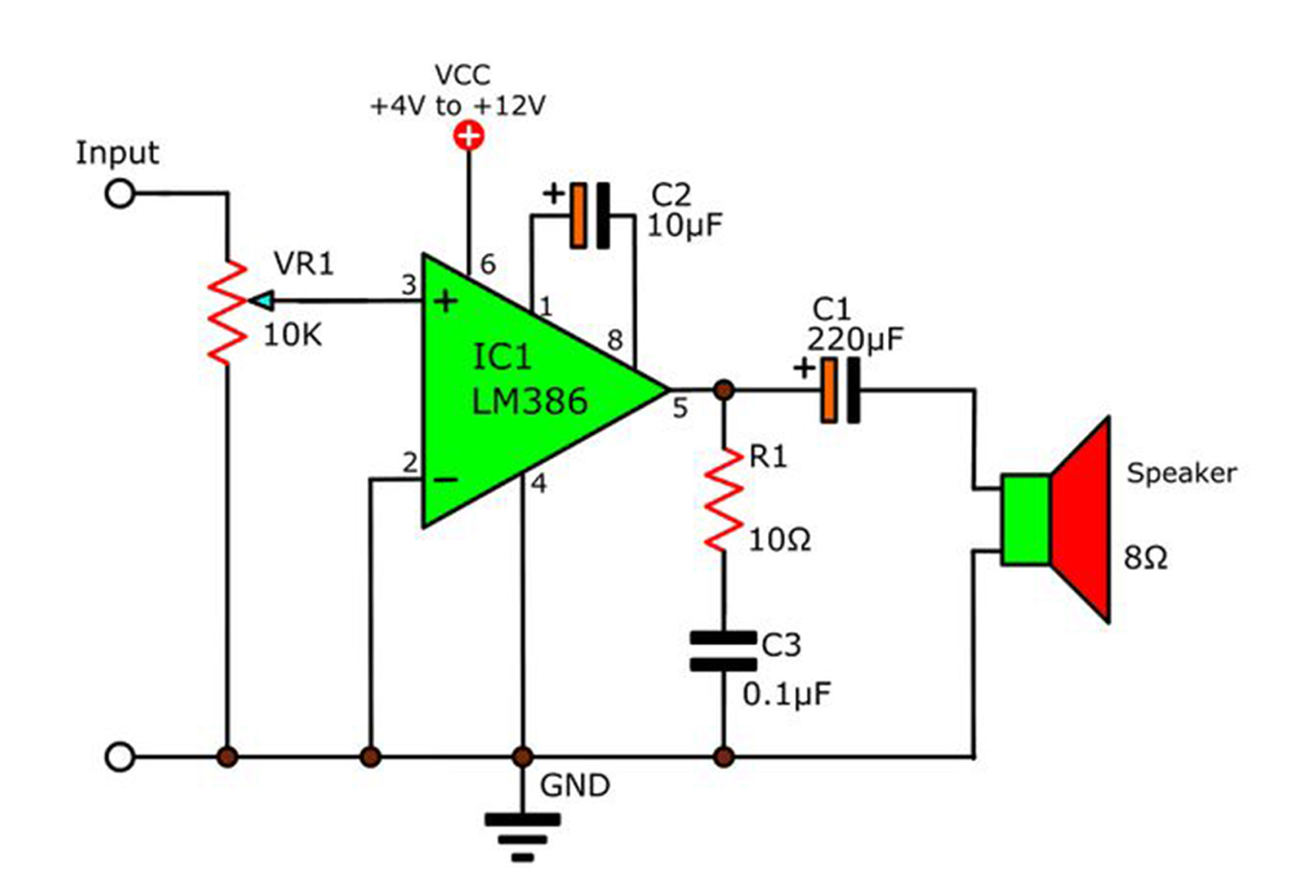
Usually an audio amplifier circuit utilizing the LM386 coordinates circuit. The input gets an sound flag, with volume controlled by the movable potentiometer (VR1). Capacitors (C1, C2, C3) are utilized for sifting to progress flag quality. The amplified sound flag is sent through a resistor (R1) and capacitor (C1) to an 8-ohm speaker for sound output. The circuit works inside a voltage extend of 4V to 12V.
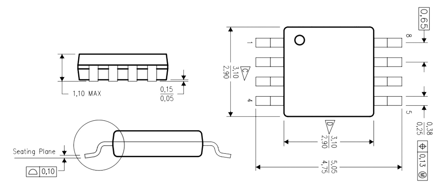
LM386 package diagram
lm386 datasheet
Summary
All in all, the LM386 remains a dependable and prevalent choice for sound applications. Understanding its key determinations, counting LM386 greatest voltage and LM386 circuit plan, will assist you utilize it to its full potential.
Commonly Asked Questions
What is the control extend of LM386 intensifier?
0.5W output control, reasonable for little speakers.What is the supply voltage of LM386?
It works between 4V to 12V.What is the pick up extend of LM386?
Pick up can be set from 20 to 200.How much calm current does LM386 utilize?
It employments 4mA in sit still mode.How is commotion sifted in LM386 circuits?
Capacitors are utilized to channel and stabilize the flag.Related Information


-

-
Phone
+86 135 3401 3447 -
Whatsapp
