 Cart ( )
Optimizing LM27403 Regulator Design: Temperature Compensated Inductor and DCR Current Sensing
2024/5/29 11:15:58
Views:

The most crucial factors for DC/DC converter systems are small size and high efficiency. As a system engineer, I know that high efficiency not only reduces power losses, but also reduces component temperature and provides more available power under given airflow and ambient temperature conditions. Compressing the answer into a tiny PCB size presents another difficulty, though.
As the demand for higher efficiency and power density continues to increase, lossless current sensing using parasitic circuit resistance becomes very valuable. According to this viewpoint, performance objectives for current mode management, multi-phase current sharing, overcurrent protection, and load current telemetry are all aided by inductor DCR current sensing technology.
Inductor DCR Current Sensing
By eliminating the power density and cost concerns associated with the use of current transformers and shunts, inductor DCR current sensing allows precise and lossless current sensing in high current converters. Merely detecting the voltage across the low-side MOSFET's RDS(ON) in a buck or boost converter is imprecise. For instance, at 25°C, the RDS(ON) is dependent upon the applied gate voltage and is not precisely stated. Similarly, sensing is only triggered when the low-side MOSFET is energized; it is not triggered when the high-side MOSFET is energized. Inductor DCR current sensing offers the advantage of continuous sensing.
Temperature Compensation
The inductor DCR sensing circuit must accommodate the known characteristics of DCR variation with temperature. Copper has a temperature coefficient of resistance (TCR) of 3930ppm/°C, which means that a 50°C temperature swing will result in a 20% change. To address this issue, a low-cost BJT can be used as a thermal diode connected remotely from the inductor, effectively achieving thermal compensation. I recently penned an article that delves deeply into this subject in light of this.
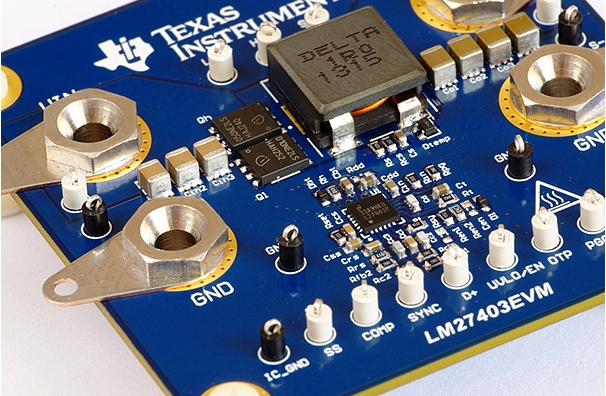
LM27403 Application
An illustration of an LM27403 buck converter with remote BJT thermal compensation and inductor DCR current detection is shown below. In point-of-load (POL) DC-DC regulator systems, the LM27403 is a feature-rich and user-friendly synchronous buck controller that provides an extraordinary degree of integration and performance to achieve high power density and efficiency.
The LM27403 features a resistor-programmable switching frequency between 200kHz and 1.2MHz, and an integrated high-current MOSFET gate driver with adaptive dead time, providing flexibility to optimize solution size and significantly improving conversion efficiency.Through the use of a 0.6V, 1% accurate voltage reference and a 30ns high-side MOSFET minimum adjustable on-time, it offers great precision and low output voltage. The LM27403 provides high-precision thermally compensated overcurrent protection (OCP) by remotely measuring the inductor temperature using a low-cost 2N3904 BJT and lossless inductor DC resistance (DCR) current sensing.
Style and Capabilities
A high-gain bandwidth error amplifier and PWM input voltage feed-forward circuitry are integrated into the LM27403's standard voltage-mode control loop, which makes compensation design easier and offers superior transient response across the whole line voltage and load current range. In sensitive applications, forced PWM (FPWM) operation reduces electromagnetic interference (EMI) and eliminates frequency fluctuations. Fault reporting and power rail sequencing are provided by an open-drain power-good circuit. Additional features include external supply tracking, configurable soft-start, programmable system-level thermal shutdown with auto-recovery, remote output voltage sensing, a low-dropout (LDO) regulator integrated into the bias supply, synchronization for beat-frequency sensitive and multi-regulator applications, and programmable line undervoltage lockout (UVLO) with custom hysteresis for precise enable. A 4mm x 4mm thermally improved WQFN-24 packaging with a 0.5mm pitch is offered for the LM27403.
Real-World Applications
A typical application schematic shows a design for driving two different solenoids (S1 and S2), the drivers are controlled by two pushbuttons connected to a 5 volt supply, and the solenoids are connected to their respective HVOUT outputs along with a small 0.1Ω resistor. In the final application, this resistor is optional and is utilized to allow the solenoid to sense external current. Pins 5 and 12 are linked to two 0.11Ω resistors for the SLG47105 current measurement. The solenoid status output is connected to a green LED and the fault output is connected to a red LED.
After a little period, the solenoid current will drop to the holding current value from the regulated peak current value. The holding current is defined as 20% of the nominal peak current, arbitrary. Based on this definition, the power dissipated in the holding current and the corresponding voltage across the sense resistor can be calculated. Table 2 displays each solenoid's optimum solenoid current, dissipated power, and sense resistor voltage.
Conclusion
The LM27403 buck regulator provides an efficient, accurate, and easy-to-use solution for a variety of point-of-load regulator applications by using inductor DCR current sensing and remote BJT for thermal compensation. Its versatile features and flexibility make it an ideal choice for achieving high power density and high efficiency. With careful design and optimization, the LM27403 is able to meet the various needs in modern power management applications, ensuring stable and reliable operation of the system.
Related Information


-

-
Phone
+86 135 3401 3447 -
Whatsapp
