 Cart ( )
FPGA VREF Parameter Optimization Strategy
2024/7/23 10:33:24
Views:
VREF Generation Circuit Optimization Method
To improve the performance of the FPGA SelectIO interface's VREF generation circuit, the following aspects can be addressed:
1. Choose an Appropriate VREF Source: In FPGA design, VREF is typically generated through external power supplies, internal regulators, or resistor dividers. Each VREF source has its characteristics and suitable scenarios. Therefore, selecting the appropriate VREF source based on specific application requirements and hardware environments is essential.
2. Design a Filtering Circuit: The SelectIO interface of an FPGA may be susceptible to noise interference from the external environment. Therefore, designing an appropriate filtering circuit in the VREF generation circuit is crucial. Proper filtering circuits can effectively suppress noise interference and enhance the stability of VREF. Common types of filtering circuits include RC filters and LC filters, which are widely used in various applications to ensure signal purity and stability.
3. Optimize PCB Layout and Routing: PCB layout and routing significantly affect the stability of VREF. The VREF generation circuit should be placed near the FPGA and use short and wide traces to reduce noise interference. Additionally, attention should be paid to isolating and shielding from other signal lines.
4. Write Verilog HDL Code for Control: By writing Verilog HDL code, precise control of the VREF generation circuit can be achieved.For case, altering the yield voltage of an inside controller or the divider proportion of a resistor divider can accurately control the VREF esteem. Moreover, the VREF esteem can be checked in real-time and balanced as required to guarantee its soundness.
The Importance of the VREF Generation Circuit
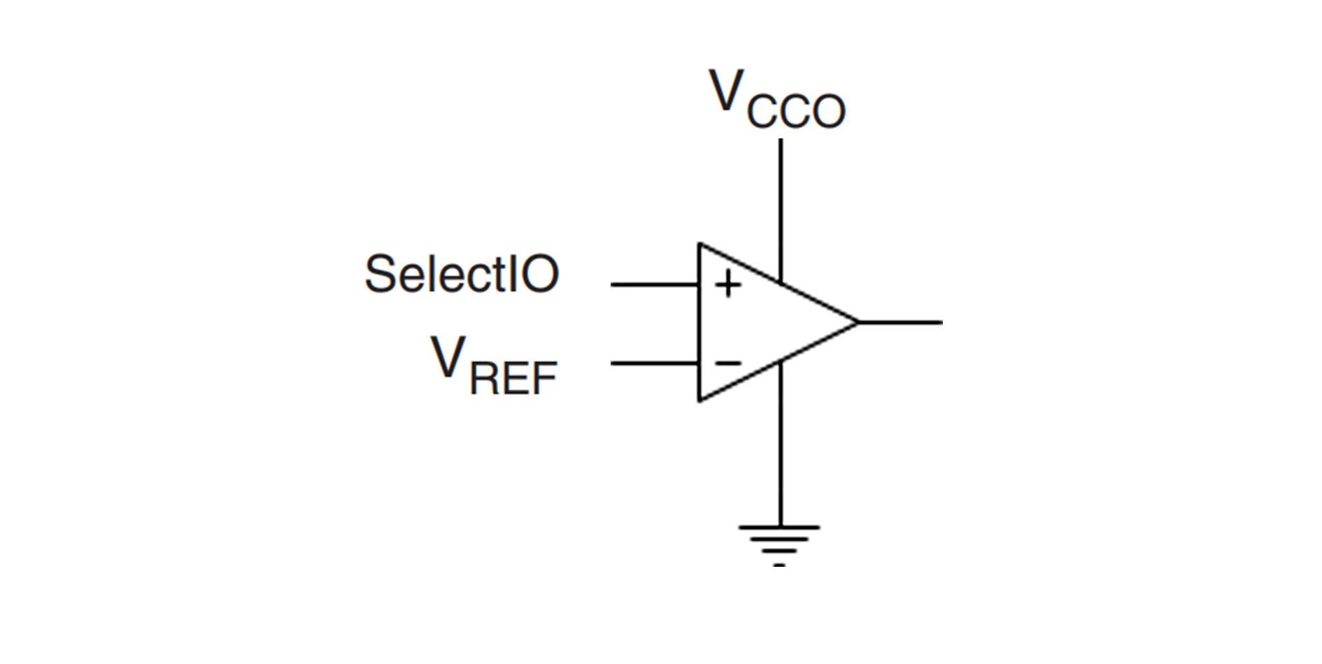
In the FPGA SelectIO interface, VREF is a crucial parameter determining the interface's voltage range and matching accuracy. An appropriate VREF value ensures voltage matching between the interface and peripherals, reducing signal reflection and distortion, thereby improving signal transmission quality. Additionally, VREF significantly impacts the interface's noise suppression ability and power consumption control. A steady VREF esteem can successfully smother clamor obstructions within the interface, make strides the signal-to-noise proportion, and accomplish exact control of interface control utilization by altering the VREF esteem, subsequently decreasing the system's by and large control utilization.
Verilog HDL Code Example
Below is a simple Verilog HDL code example for generating a stable VREF value in an FPGA:
```verilog
module VREF_Generator(
input wire clk, // Clock signal
input wire rst_n, // Reset signal
output reg vreg_out // Generated VREF output
);
const int vreg_target = 1200; // Assume VREF target value is 1.2V (in mV)
reg [11:0] vreg_current = 0; // Assume using 12-bit precision to represent VREF value (0-4095 corresponds to 0-VREF_MAX)
always @(posedge clk or negedge rst_n) begin
if (!rst_n) begin
vreg_current <= vreg_target >> 12; // Set VREF to initial value on reset
end else begin
// Adjust vreg_current value based on some algorithm or condition in each clock cycle
// Actual application needs to be adjusted based on specific conditions
end
end
assign vreg_out = vreg_current / 4095.0 * VREF_MAX; // Assume VREF_MAX is the maximum available VREF voltage value
endmodule
Optimizing the FPGA SelectIO Interface VREF Generation Circuit: Design and Implementation
This article will delve into how to optimize the VREF generation circuit of the FPGA SelectIO interface to enhance interface performance and stability, along with corresponding Verilog HDL code examples.
Through this introduction, we hope to provide readers with some ideas and methods for optimizing the VREF generation circuit of the FPGA SelectIO interface for application and improvement in actual design.
Please note that the above code is just a simple example to illustrate how to generate a stable VREF value in an FPGA. In actual applications, adjustments and optimizations need to be made based on specific hardware environments and application requirements.
Related Information


-

-
Phone
+86 135 3401 3447 -
Whatsapp
