Application of Dual-Loop Clock Generator in Electronic Systems
2024/8/8 15:39:13
Views:
In advanced electronic frameworks, the steadiness and accuracy of clock signals are vital for framework execution. With the ceaseless advancement within the speed and determination of information converters, the request for high-frequency, low-phase clamor clock sources is expanding. Particularly in applications such as cellular base stations, military radar frameworks, and other high-speed, high-performance clock flag necessities, the plan of clock generators gets to be especially vital. Dual-loop clock generators, as an progressed clock era innovation, through their interesting structure and work, not as it were successfully kill jitter but too give different high-frequency, low-phase commotion yields, making them an perfect choice for high-end applications.
Basic Principles
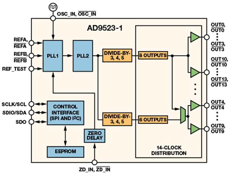
Dual-loop clock generators ordinarily comprise of two cascaded phase-locked circles (PLLs), specifically PLL1 and PLL2. This auxiliary plan points to combine the points of interest of low-frequency and high-frequency PLLs to attain higher execution and adaptability.

PLL1 (Low-Frequency PLL):
Primarily responsible for eliminating reference jitter. It employments an outside low-frequency voltage-controlled precious stone oscillator (VCXO) and an implanted third-order circle channel to create a PLL with a circle transmission capacity within the run of 30 Hz to 100 Hz. The limit transfer speed plan permits PLL1 to viably channel out high-frequency commotion and jitter from the reference input, yielding a low-phase clamor clock flag.
PLL2 (High-Frequency PLL):
Responsible for generating high-frequency phase-aligned outputs. It integrates a high-speed voltage-controlled oscillator (VCO) with a center frequency of up to several GHz and part of the embedded third-order loop filter, with a loop bandwidth usually around a few hundred kHz. PLL2 uses the low-phase noise clock signal provided by PLL1 as a reference to further generate high-frequency, phase-aligned outputs.
Advantages
Jitter Elimination:
A single high-frequency PLL, although capable of frequency conversion, is challenging to design with a sufficiently low loop bandwidth to filter out the impact of high-noise references. The dual-loop structure, with PLL1's narrow bandwidth design, effectively attenuates the reference input phase noise, significantly reducing output clock jitter, making the entire system's clock signal more stable and reliable.
High-Frequency Output:
On the basis of jitter elimination, PLL2 uses a high-speed VCO to generate high-frequency, phase-aligned outputs. This high-frequency output not only meets the clock frequency requirements of modern electronic systems but also maintains low-phase noise characteristics, ensuring high-performance system operation.
Multi-Output Capability:
Some modern dual-loop analog PLLs are integrated into a single chip, allowing designers to provide clock signals to multiple devices requiring different frequencies from a single phase-aligned source. This design not only saves valuable PCB space but also simplifies system design and improves overall system performance.
Low Phase Noise:
Dual-loop clock generators achieve overall low phase noise output by optimizing PLL loop bandwidth and VCO/VCXO phase noise curves. This is particularly important for applications requiring high-precision time synchronization and frequency stability.
Application Examples and Performance Analysis
Taking clock generators such as AD9523, AD9523-1, and AD9524 as examples, these devices all use dual-loop structures. In the AD9523-1, PLL1 uses an external low-frequency VCXO and part of an embedded third-order loop filter to form a PLL with a loop bandwidth in the range of 30 Hz to 100 Hz. This PLL, through high-performance VCXO and low loop bandwidth design, effectively attenuates reference input phase noise. PLL2, on the other hand, uses an internal high-speed VCO centered at 3 GHz and part of an embedded third-order loop filter to generate high-frequency, phase-aligned outputs.
In practical applications, the performance of dual-loop clock generators is remarkable. Through validation using the ADIsimCLK simulation tool, results show that PLL1's output phase noise is significantly lower than the original reference input phase noise, and its loop bandwidth significantly attenuates the reference voltage source phase noise. At high frequencies, PLL2's internal VCO phase noise becomes the dominant factor, but within a certain range (e.g., after 5 kHz offset frequency), its impact is limited. Therefore, dual-loop clock generators can provide stable, low-phase noise clock signals over a wide frequency band.
Conclusion
Dual-loop clock generators, with their interesting structure and amazing execution, are playing an progressively imperative part in cutting edge electronic frameworks. By combining the preferences of low-frequency and high-frequency PLLs, dual-loop clock generators not as it were viably dispose of jitter but too give different high-frequency, low-phase clamor yields. This design not only meets the high requirements of modern electronic systems for clock signals but also simplifies system design and improves overall system performance. With continuous technological advancements and expanding application fields, the application prospects of dual-loop clock generators will become even broader.
Related Information
-
-
Phone
+86 135 3401 3447 -
Whatsapp


