 Cart ( )
In-depth analysis: A practical guide to conditioning CAN signal output using basic circuits
2024/5/22 11:16:00
Views:
In today's automotive electronic systems, CAN (Controller Area Network) bus technology has been widely used due to its high reliability, fast speed and strong flexibility. The CAN bus uses a differential signal transmission method to ensure the anti-interference of the signal during transmission. However, in some special cases, such as laboratory testing or custom equipment, a simple and adjustable CAN level differential output signal source may be required. Therefore, this article aims to introduce how to use a simple circuit design to achieve this requirement.
Design ideas
In order to achieve an adjustable CAN level differential output signal, it is necessary to design a circuit that can generate a differential signal. The circuit needs to meet the following conditions:
The common mode voltage of the differential signal needs to be stable at about 2.5V;
The differential voltage needs to be adjustable, that is, the voltage difference between CAN_H and CAN_L;
The range of the differential voltage should be within the range allowed by the CAN bus.
Based on the above conditions, the following design schemes can be adopted:
Use a regulated power supply to generate a stable common mode voltage;
Change the differential voltage by adjusting the resistor divider network;
Use a differential amplifier to amplify the differential signal to meet the CAN bus level requirements.
Circuit Design
Common-mode voltage generation circuit
In order to generate a stable common-mode voltage, a voltage regulator (such as LM7805) can be used to provide a 5V voltage. Then, the 5V voltage is reduced to 2.5V through a resistor divider network as the common-mode voltage. In order to improve voltage stability, a capacitor can be connected in parallel to the voltage divider network to reduce ripple.
Differential voltage generation circuit
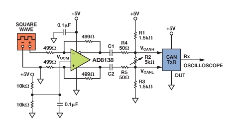
The differential voltage generation circuit is mainly composed of a resistor divider network and a differential amplifier. The resistor divider network consists of two adjustable resistors, and the differential voltage is changed by adjusting the resistance values of the two resistors. The differential amplifier uses an operational amplifier (such as LM358) to amplify the differential signal. In order to obtain the required differential voltage range, it is necessary to select a suitable amplification factor and resistance value.
Differential amplifier circuit
The differential amplifier circuit adopts a dual-end input and single-end output method. The input end is connected to the differential signal generated by the resistor divider network, and the output end is connected to the CAN_H and CAN_L lines. In the design, it is necessary to pay attention to parameters such as the common-mode rejection ratio and bandwidth of the differential amplifier to ensure that its ability to suppress common-mode signals and the signal transmission bandwidth meet the requirements.
Circuit Implementation and Testing
Circuit Implementation
Based on the above design ideas, you can draw a circuit schematic and use electronic production tools to make a circuit board. To guarantee the stability and dependability of the circuit, you must pay close attention to the component arrangement and welding quality during the production process.
Circuit Test
After the circuit is completed, it is necessary to test it to verify its performance. First, use an oscilloscope to measure the stability of the common-mode voltage and the differential voltage; then, observe the range of variation of the differential voltage by changing the resistance value of the adjustable resistor; finally, connect the circuit to the CAN bus for actual testing to observe the stability and correctness of the signal transmission.
CAN bus signal characteristics
The CAN bus adopts differential signal transmission, that is, the signals transmitted on the CAN_H and CAN_L lines are inverted. When the voltage of CAN_H is higher than that of CAN_L, it indicates logic "1"; when the voltage of CAN_H is lower than that of CAN_L, it indicates logic "0". The level range of the CAN bus is usually between 2.5V and 3.5V for CAN_H and between 1.5V and 2.5V for CAN_L. In the recessive state (when no signal is transmitted), the levels of CAN_H and CAN_L are similar, close to the common mode voltage (about 2.5V).
Conclusion
This paper introduces a method of using a simple circuit to realize an adjustable CAN level differential output signal. By designing the common mode voltage generation circuit, the differential voltage generation circuit and the differential amplifier circuit, a stable and adjustable CAN level differential output signal source can be obtained. The circuit has the advantages of simple structure, low cost and easy implementation, and is suitable for special applications such as laboratory testing or customized equipment.
Design ideas
In order to achieve an adjustable CAN level differential output signal, it is necessary to design a circuit that can generate a differential signal. The circuit needs to meet the following conditions:
The common mode voltage of the differential signal needs to be stable at about 2.5V;
The differential voltage needs to be adjustable, that is, the voltage difference between CAN_H and CAN_L;
The range of the differential voltage should be within the range allowed by the CAN bus.
Based on the above conditions, the following design schemes can be adopted:
Use a regulated power supply to generate a stable common mode voltage;
Change the differential voltage by adjusting the resistor divider network;
Use a differential amplifier to amplify the differential signal to meet the CAN bus level requirements.
Circuit Design
Common-mode voltage generation circuit
In order to generate a stable common-mode voltage, a voltage regulator (such as LM7805) can be used to provide a 5V voltage. Then, the 5V voltage is reduced to 2.5V through a resistor divider network as the common-mode voltage. In order to improve voltage stability, a capacitor can be connected in parallel to the voltage divider network to reduce ripple.
Differential voltage generation circuit
The differential voltage generation circuit is mainly composed of a resistor divider network and a differential amplifier. The resistor divider network consists of two adjustable resistors, and the differential voltage is changed by adjusting the resistance values of the two resistors. The differential amplifier uses an operational amplifier (such as LM358) to amplify the differential signal. In order to obtain the required differential voltage range, it is necessary to select a suitable amplification factor and resistance value.
Differential amplifier circuit
The differential amplifier circuit adopts a dual-end input and single-end output method. The input end is connected to the differential signal generated by the resistor divider network, and the output end is connected to the CAN_H and CAN_L lines. In the design, it is necessary to pay attention to parameters such as the common-mode rejection ratio and bandwidth of the differential amplifier to ensure that its ability to suppress common-mode signals and the signal transmission bandwidth meet the requirements.
Circuit Implementation and Testing
Circuit Implementation
Based on the above design ideas, you can draw a circuit schematic and use electronic production tools to make a circuit board. To guarantee the stability and dependability of the circuit, you must pay close attention to the component arrangement and welding quality during the production process.
Circuit Test
After the circuit is completed, it is necessary to test it to verify its performance. First, use an oscilloscope to measure the stability of the common-mode voltage and the differential voltage; then, observe the range of variation of the differential voltage by changing the resistance value of the adjustable resistor; finally, connect the circuit to the CAN bus for actual testing to observe the stability and correctness of the signal transmission.
CAN bus signal characteristics
The CAN bus adopts differential signal transmission, that is, the signals transmitted on the CAN_H and CAN_L lines are inverted. When the voltage of CAN_H is higher than that of CAN_L, it indicates logic "1"; when the voltage of CAN_H is lower than that of CAN_L, it indicates logic "0". The level range of the CAN bus is usually between 2.5V and 3.5V for CAN_H and between 1.5V and 2.5V for CAN_L. In the recessive state (when no signal is transmitted), the levels of CAN_H and CAN_L are similar, close to the common mode voltage (about 2.5V).
Conclusion
This paper introduces a method of using a simple circuit to realize an adjustable CAN level differential output signal. By designing the common mode voltage generation circuit, the differential voltage generation circuit and the differential amplifier circuit, a stable and adjustable CAN level differential output signal source can be obtained. The circuit has the advantages of simple structure, low cost and easy implementation, and is suitable for special applications such as laboratory testing or customized equipment.
Related Information


-

-
Phone
+86 135 3401 3447 -
Whatsapp
