 Cart ( )
Bridge Sensor Circuit Challenges and Optimization
2024/9/7 10:30:20
Views:
Bridge sensors are widely used in industrial automation, environmental monitoring, and biomedical fields, and are highly favored for their high precision characteristics. However, complex issues such as insufficient signal gain, common-mode voltage interference, and DC offset in circuit design often pose challenges for designers. This article aims to explore key design methods to help avoid these problems.
Signal Gain and Amplifier Selection
The yield flag of a bridge sensor is ordinarily little, requiring a high-gain intensifier to boost the flag quality for consequent computerized handling or control. When selecting an intensifier, consideration must be paid to its pick up, commotion level, and common-mode dismissal proportion (CMRR). For example, precision instrumentation amplifiers are ideal for suppressing common-mode voltage at the input during signal amplification, making them a preferred choice. Instrumentation amplifiers such as the AD8237 and AD8420, which use indirect current feedback (ICF), are particularly suitable for low-power bridge circuit applications.
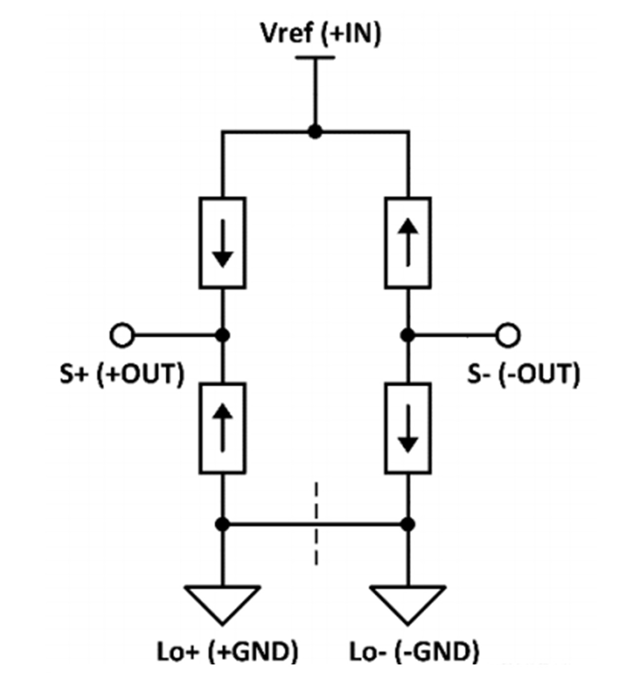
Understanding the Basic Principles of Bridge Sensors
The Wheatstone bridge is a typical bridge sensor, which senses physical quantities through changes in resistance. When the four resistances are completely identical, the output of the bridge is zero. However, manufacturing errors and external environmental factors often lead to offset voltages. This offset voltage can directly affect measurement accuracy, so it must be addressed in the design.
Suppressing DC Offset and Common-Mode Voltage
In design, common-mode voltage and DC offset are inevitable. Common-mode voltage is caused by environmental noise and other factors, while DC offset is related to resistor tolerances and temperature changes. Differential amplifiers and ICF instrumentation amplifiers can effectively suppress common-mode voltage, maintaining high-precision signal output. Applying reverse voltage to the REF terminal is another common method, which is effective for large input offsets but ineffective when the first stage of the amplifier is saturated.
Circuit Design Optimization and Offset Calibration
For bridge offset, traditional solutions like external resistor shunting are useful but not suitable for large-scale automated production. Digital correction is another solution, reducing the first-stage gain and removing the offset via software. However, a more cutting-edge solution is the use of ICF instrumentation amplifiers like the AD8237, which can precisely adjust DAC to fine-tune bridge offset. This not only allows for adjustment during production but also accommodates environmental changes for real-time re-adjustment.
Power Supply Design and Optimization
A well-designed power supply and ground layout are crucial for suppressing noise and interference. Using low-noise power supplies and proper ground layouts can reduce signal interference and errors. Additionally, attention should be paid to selecting appropriate resistor values in the design to avoid power consumption and noise issues that could affect circuit performance.
Conclusion
In summary, bridge sensor circuit design needs to consider factors such as signal gain, common-mode interference suppression, bridge offset calibration, and circuit layout. Through proper design and optimization, complex problems can be effectively avoided, improving measurement accuracy and system reliability.
Related Information


-

-
Phone
+86 135 3401 3447 -
Whatsapp
