 Cart ( )
BNO055 Sensor and BNO055 Breakout Board: Quick Setup Guide
2024/10/16 15:16:13
Views:
The BNO055 is a 9-axis absolute orientation sensor that integrates an accelerometer, gyroscope, and magnetometer, making it ideal for projects requiring precise orientation tracking. It's widely used in robots, drones, and wearables, simplifying sensor fusion by providing direct orientation data. This article provides a brief guide on setting up the BNO055 breakout board, interfacing it with popular microcontrollers, and key information on its pinout and features.
Bosch Sensortec Tutorials: How to calibrate the absolute orientation sensor BNO055
Table of Contents
- What is the BNO055 Sensor?
- Interfacing the BNO055 with Arduino
- I²C connection of the BNO055 sensor
- Calibrating the BNO055 Sensor
- Applications of the BNO055 Sensor
- BNO055 Price Range
- BNO055 Alternatives
- Conclusion
- Commonly Asked Questions
What is the BNO055 Sensor?
The BNO055 sensor, created by Bosch, may be a keen sensor that combines the usefulness of an accelerometer, magnetometer, and spinner into one bundle. Whereas most sensors give crude information, the BNO055 goes a step advance by executing sensor combination calculations inside. It outputs ready-to-use orientation data such as Euler angles or quaternions, making it ideal for applications requiring fast and accurate orientation tracking.
Why Choose the BNO055?
The BNO055 is favored for its ease of use in projects where real-time orientation data is crucial. Compared to raw data sensors, the BNO055 requires less post-processing and code on the microcontroller side, as it performs sensor fusion internally.
BNO055 Pinout
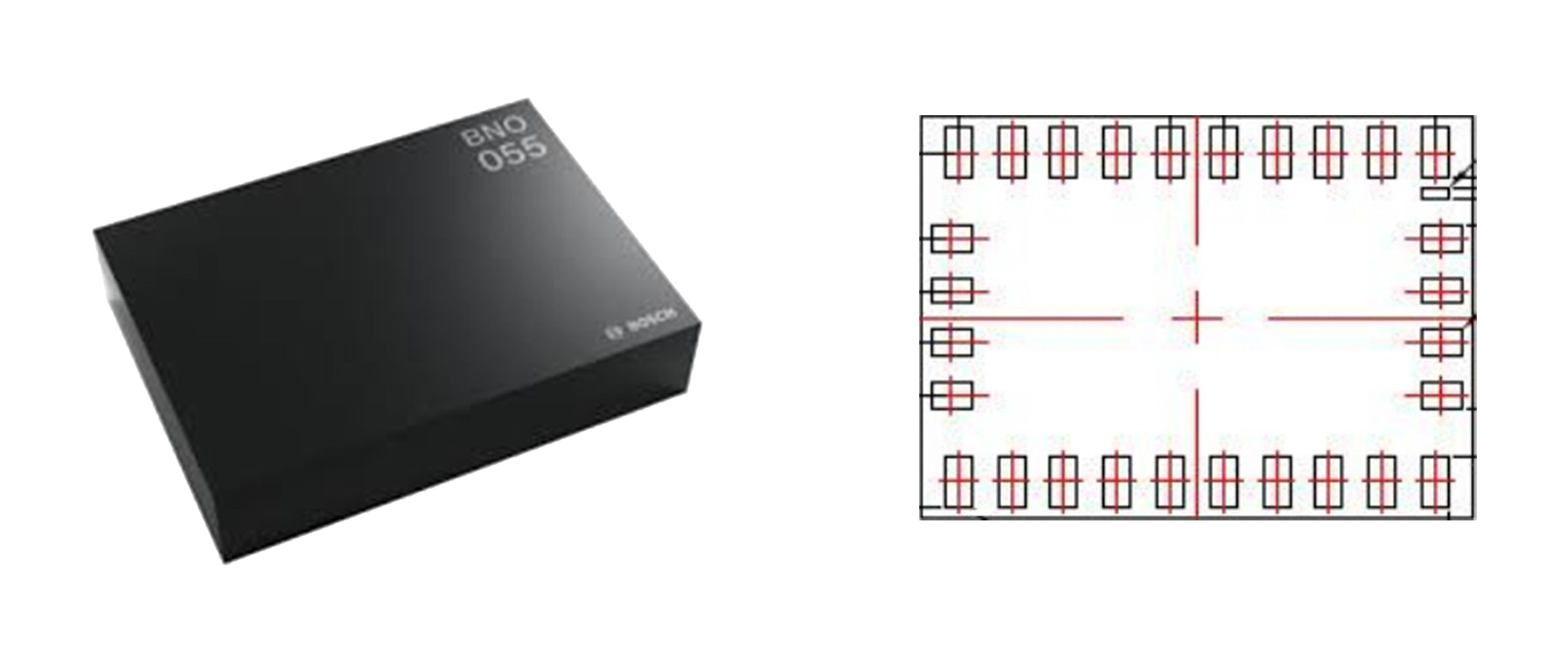
The BNO055 breakout board has several pins that you need to connect properly to your microcontroller. Here's the BNO055 Pinout for reference:
This simple pin configuration allows for flexible interfacing with various microcontrollers, such as the Arduino and ESP32.
Key Features of the BNO055
- 9-axis absolute orientation: Combines accelerometer, magnetometer, and gyroscope data to output orientation directly.
- Sensor fusion: Internal algorithms provide fused orientation without the need for external computation.
- Multiple output formats: Supports Euler angles, quaternions, linear acceleration, and gravity vector.
- Configurable operation modes: You can select individual sensor data or the fused output.
- Built-in calibration: The sensor naturally calibrates over time, moving forward precision.
Interfacing the BNO055 with Arduino
One of the foremost common employments of the BNO055 is with Arduino. To induce begun with bno055 arduino ventures, take after these steps:
Step 1: Gather Components
- BNO055 breakout board
- Arduino (or any other compatible Arduino board)
- Jumper wires
- Breadboard
- USB cable for programming
Step 2: Wiring the BNO055 to Arduino

For I2C communication, connect the pins as follows:
- Vin is connected to 5V on the Arduino.
- GND is connected to GND on the Arduino.
- SCL is connected to A5 on the Arduino Uno (which is the I²C clock pin).
- SDA is connected to A4 on the Arduino Uno (which is the I²C data pin).
Step 3: Install Libraries
Install the Adafruit BNO055 library via the Arduino IDE. Go to Sketch > Include Library > Manage Libraries, search for Adafruit BNO055, and install it.
Step 4: Load Example Code
Once the library is installed, go to File > Examples > Adafruit BNO055 > sensorapi to load a basic example that demonstrates how to read data from the sensor.
Step 5: Upload Code and Monitor Output
Upload the code to your Arduino and open the serial monitor. You should see orientation data such as Euler angles or quaternions being printed, which represents the real-time orientation of the sensor.
I²C connection of the BNO055 sensor
The BNO055 is an intelligent 9-axis sensor that integrates an accelerometer, gyroscope, and magnetometer. The diagram above shows how to connect the BNO055 using the I²C communication protocol.

Key connection points:
- VDDIO and VDD are power supply pins that ought to be associated to a 3.3V or 5V source, depending on your framework voltage prerequisites.
- GND is the ground pin and ought to be associated to the framework ground.
- SCL (Clock Line) and SDA (Data Line) are the two communication lines utilized for I²C communication. Both lines ought to be associated to the microcontroller's comparing I²C pins. Typically, pull-up resistors (10kΩ) are needed on these lines to ensure proper communication.
- PS1 and RBOOT_LOAD manage boot and startup procedures for the BNO055.
- I2C_ADDR_SEL allows you to select the I²C address for the BNO055, useful when working with multiple devices on the same I²C bus.
- INT pin is used for the interrupt function, signaling specific events or data availability.
- nRESET is the reset pin, permitting you to reset the BNO055 when required.
This association is fundamental for meddle the BNO055 sensor with a microcontroller or advancement board, such as an Arduino or Raspberry Pi, for introduction, movement following, or virtual reality applications.
Calibrating the BNO055 Sensor
The image shows 6 stable positions for accelerometer calibration. Each position aligns the sensor's axes (X, Y, Z) with the direction of gravity. Here is a detailed description of the positions:

Position:
- Z-axis is indicating up, X-axis is level, and Y-axis is vertical.
- Z-axis is indicating down, X-axis is even, and Y-axis is indicating up.
- Y-axis is level, X-axis is vertical indicating up, and Z-axis is vertical.
- X-axis is vertical, Y-axis is flat, and Z-axis is indicating up.
- X, Y, and Z-axes are all even in a level introduction.
- X, Y, and Z-axes form a 3D cube structure showing different calibration angles for the accelerometer.
Calibration Steps:
- Magnetometer Calibration: Slowly rotate the sensor in all axes to complete the magnetometer calibration.
- Accelerometer Calibration: Keep the sensor in each of the six steady positions on a level surface to guarantee exact accelerometer calibration.
- Gyroscope Calibration: The Gyroscope will consequently calibrate when the sensor is kept still.
This description matches the image, explaining the stable positions used for accelerometer calibration.
Applications of the BNO055 Sensor
The BNO055 sensor's capacity to track introduction precisely in 3D space makes it an fabulous choice for different applications. Let's explore some common use cases:
Robotics and Drones
Robots and drones need to know their exact orientation to navigate correctly. The BNO055 orientation data helps maintain balance, ensure correct turns, and provide smooth movement. For drones, this sensor is crucial for stabilizing flight.
Wearables and Motion Tracking
In wellness trackers, smartwatches, and other wearables, the BNO055 module can screen client introduction and development. It can moreover track real-time pose, guaranteeing precise criticism amid workouts or exercises like yoga.
Virtual and Augmented Reality
In AR/VR headsets, the bno055 absolute orientation sensor tracks the user's head development, guaranteeing a consistent encounter when association with virtual situations.
BNO055 Price Range
The BNO055 sensor is broadly accessible from different electronics retailers and online stages. The BNO055 price regularly ranges between $25 and $40, depending on the retailer and the particular breakout board form you're obtaining. It's basic to compare costs and consider whether you wish extra highlights like pre-soldered headers or a specific shape figure when selecting the correct module for your venture.
BNO055 Alternatives
For BNO055 choices, you'll consider sensors just like the MPU-9250 or BMX055. These moreover coordinated accelerometers, whirligigs, and magnetometers, giving 9-axis movement following and introduction location.
Conclusion
The BNO055 sensor and BNO055 breakout board are important apparatuses for any venture requiring precise introduction following. Whether you're utilizing it with an Arduino or ESP32, the setup handle is basic and clear. Its capacity to perform inside sensor combination and yield ready-to-use introduction information makes it a effective resource for mechanical autonomy, wearables, rambles, and more. With simple accessibility and flexible applications, the BNO055 may be a must-have for electronics devotees.
Commonly Asked Questions
What is the key advantage of the BNO055 sensor?
The BNO055 coordinating sensor combination, giving ready-to-use introduction information, not at all like crude information sensors.How do you calibrate the BNO055 sensor?
Calibration requires pivoting the sensor for the magnetometer, holding steady positions for the accelerometer, and keeping it still for the spinner.Which microcontrollers bolster the BNO055 breakout board?
It is congruous with Arduino, ESP32, and Raspberry Pi through I²C or SPI communication.What is the working voltage for the BNO055 sensor?
It works between 2.4V and 3.6V.How does the BNO055 breakout board rearrange integration?
It offers pre-configured I²C/SPI pins, making it simple to associate to microcontrollers without additional sensor combination coding.Related Information


-

-
Phone
+86 135 3401 3447 -
Whatsapp
