 Cart ( )
1N4148 Signal Fast Switching Diode: Datasheet and Equivalent
2024/12/25 11:27:35
Views:
This article will introduce the technical specifications and main applications of 1N4148 diodes in detail, and compare them with common diodes such as 1N914 and 1N4007 to help you gain a deeper understanding of 1N4148's operating principle, characteristics and applicable scenarios.
DIODE PARAMETERS | EXAMPLE WITH 1N4148
- What is 1N4148 Diode?
- 1N4148 Diode Specifications
- 1N4148 Diode Pinout & Symbol and Footprint
- 1N4148 Diode Working Principle
- 1N4148 Diode Applications
- 1N4148 Diode Equivalent and Alternatives
- Comparison: 1N4148 vs Other Diodes
- 1N4148 Diode package
- 1N4148 Diode Datasheet PDF
What is 1N4148 Diode?
The 1N4148 is a small signal silicon diode with a low forward voltage drop (~0.7V), fast switching speed, and short reverse recovery time. These characteristics make it excellent in high frequency circuits and low current signal processing. It is widely used in digital and pulse circuits for fast signal switching and efficient transmission. In addition, the 1N4148 is used in signal rectification, voltage clamp protection, and clipping circuit to provide stable performance.
1N4148 Diode Specifications
Type: Fast switching diode (signal diode)
Reverse Voltage (V_R): 100V(Breakdown voltage)
Forward Voltage Drop: 0.7V (typical at 10mA)
Reverse Leakage Current: 25nA (at 100V reverse bias)
Reverse Recovery Time(t_rr): 4 ns (typical)
Capacitance: 4pF (at 0V reverse bias)
Maximum Forward Current: 300 mA
Max Operating Frequency: 100 MHz
Operating Temperature: -65°C to 150°C
Package Type: DO-35 Glass (through hole) and SMD package (e.g. SOD-123, SOD-323)
1N4148 Diode Pinout & Symbol and Footprint
The pin configuration of the 1N4148 diode clearly shows its polarity, as illustrated in the diagram below. The anode is usually unmarked, while the cathode is identified by a black stripe (circle) on the body of the tube to indicate the direction of current flow. In the circuit symbol, the direction of the arrow indicates the positive conduction state of current flow from the anode to the cathode, and the horizontal line represents the cathode.

1N4148 Pinout

1N4148 Symbol
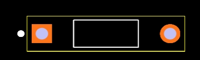
1N4148 Footprint
1N4148 Diode Working Principle
The operating principle of the 1N4148 diode is based on its internal PN junction structure. Depending on the direction of the externally applied voltage, the diode can be forward or reverse biased.
PN junction and Depletion Region
The PN junction inside the 1N4148 diode forms a depletion region that prevents current flow.
Forward bias: When the diode is forward biased, the depletion region narrows and current can flow from the anode to the cathode.
Reverse bias: When the diode is reverse biased, the depletion region widens and current is prevented from flowing.
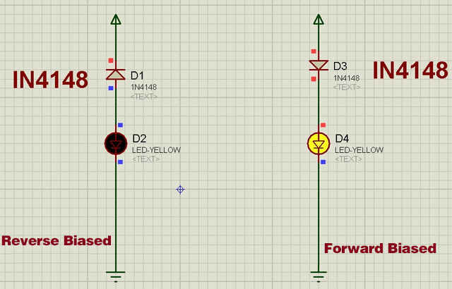
1N4148 Working Principle
Forward Bias
When a forward voltage is applied (i.e., the anode is positively charged and the cathode is negatively charged), the 1N4148 enters a forward bias state. In this state, the depletion region of the PN junction narrows and current can pass through the diode.
Conduction conditions: When the forward voltage exceeds a threshold of about 0.7V (this value applies to silicon diodes), the diode starts to conduct and current can flow from the anode to the cathode.
For example, in the circuit on the right side of the figure, the 1N4148 diode (D3) allows current to flow through the yellow LED (D4), causing it to light up. The red dynamic symbol in the circuit indicates that the circuit is closed and switched on under forward bias.
Reverse Bias
The 1N4148 enters the reverse bias state when a reverse voltage is applied (i.e., the anode is negatively charged and the cathode is positively charged). In this state, the depletion region of the PN junction is widened and the diode forms a strong reverse electric field, inhibiting current flow.
Reverse Current: Under normal reverse bias, the reverse current is very small, typically about 25nA, so the 1N4148 diode does not conduct under normal conditions. For example, in the circuit on the left side of the diagram, The 1N4148 diode (D1) prevents current flow and the yellow LED (D2) remains off, indicating that the diode is not conducting. The red dynamic symbol indicates that the circuit is open, emphasizing that no current flows under reverse bias.
Reverse Breakdown: If the applied reverse voltage exceeds the maximum reverse voltage of the diode (approximately 100V), reverse breakdown may occur, resulting in a dramatic increase in current and possible damage to the diode. Reverse breakdown is usually a destructive phenomenon, so exceeding the maximum reverse voltage specification of the diode should be avoided.
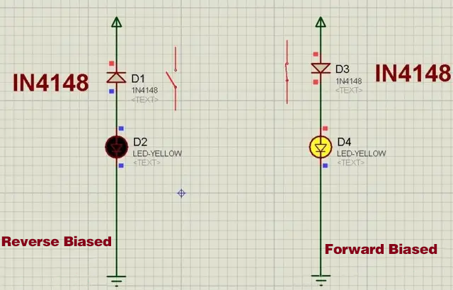
1N4148 Bias Simulation
1N4148 Diode Applications
Signal Switching: high speed switching applications,such as digital logic circuits or RF signal processing.
Clipping and Clamping: clipping circuits to limit the voltage level of a signal, or as a clamping diode to protect circuits from voltage spikes.
Oscillators: Various oscillator circuits requiring fast switching and minimal delay.
Temperature Sensing: The 1N4148 can be used as a temperature sensor temperature sensor because its forward voltage decreases with increasing temperature. As the temperature rises, the forward voltage drops at a rate of about -2 mV/°C, and the temperature can be determined by measuring the voltage change.
To use the 1N4148 as a temperature sensor, you can connect it in series with a resistor to form a voltage divider circuit. This allows you to measure the voltage change and calculate the corresponding temperature.
Circuit Design:
1N4148 Diode (D1): acts as a temperature sensing element, the forward voltage varies with temperature.
Resistor (R2): Together with the diode, forms a voltage divider that generates a temperature dependent signal.
Operational amplifier (IC1 - 741): amplifies the signal to make temperature measurement easier.
Adjustable Resistors (VR1, VR2): used to adjust the zero and gain to ensure accurate output.
Zener diode (ZD1): provides a stable reference voltage for the operational amplifier.
As the temperature increases, the voltage drop across the diode decreases, resulting in a measurable signal that is amplified by the op-amp. The output (Vout1) can be connected to an Arduino or similar microcontroller for temperature monitoring. The circuit is calibrated using a 1N4148 temperature profile and is suitable for thermometers and basic temperature sensing applications.
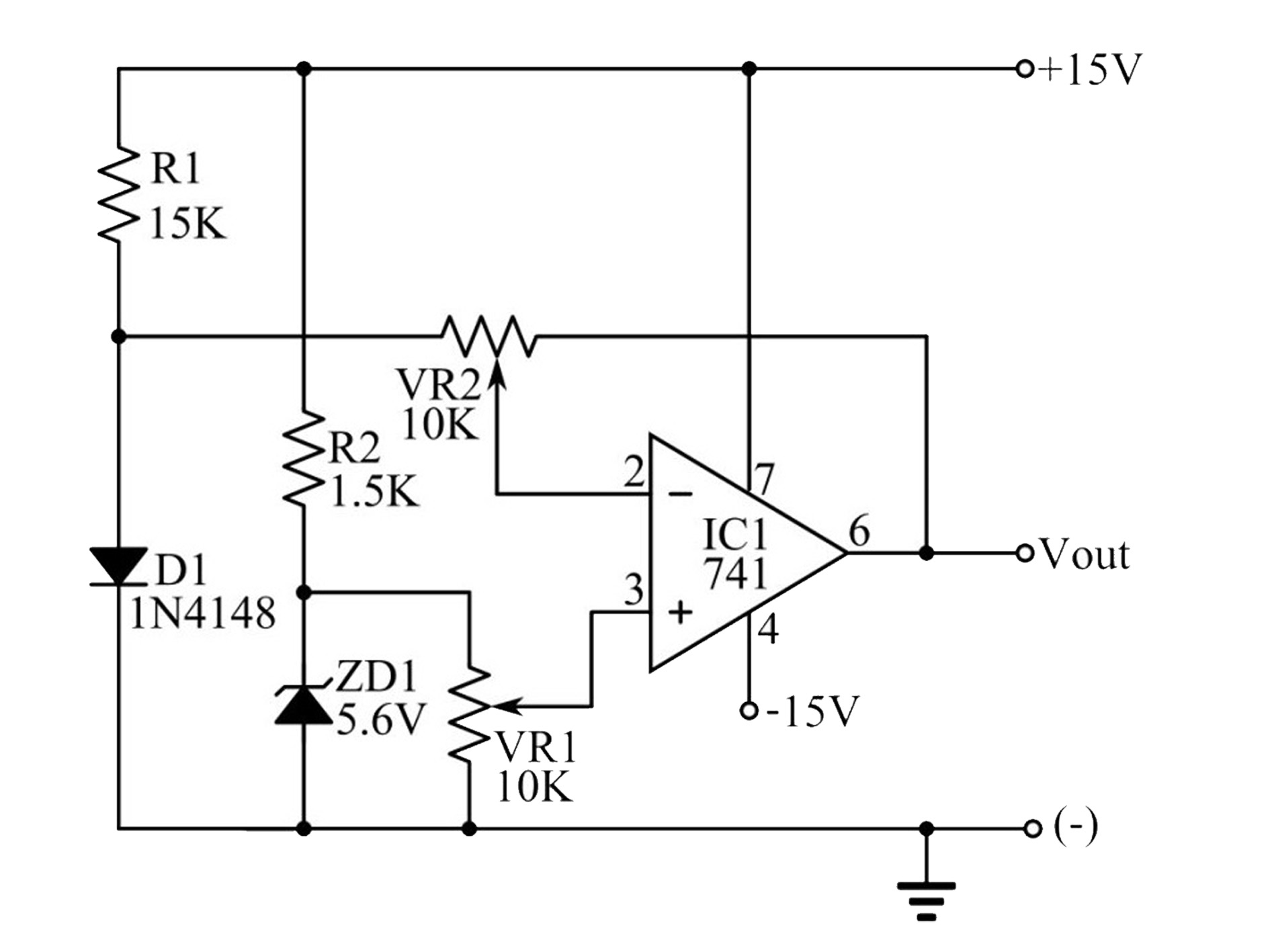
1n4148 temperature sensor circuit
1N4148 Diode Equivalent and Alternatives
Several diodes with similar electrical characteristics can replace the 1N4148.
Common substitute diodes include the 1N914, 1N914B, IN914A, 1N916A, 1N916, 1N916B, 1N4448WS, 1N4448, 1N4148WS and 1N4448W.
Comparison: 1N4148 vs Other Diodes
1N914 vs 1N4148: Both are fast switching diodes, but the 1N4148 has a higher reverse voltage rating (100V) than the 1N914 (75V). This makes the 1N4148 more suitable for circuits requiring higher reverse voltage tolerance.
1N4007 vs 1N4148: The 1N4007 is a general purpose rectifier diode rated at 1A, while the 1N4148 is a small-signal, fast-switching diode with a maximum current of 300mA. 1N4148 is more suited for low-current, high speed applications, while 1N4007 is suitable for power supply rectification.
1N4448 vs 1N4148:The 1N4448 is nearly identical to the 1N4148, but the 1N4448 has a slightly longer reverse recovery time. For most general purpose switching applications, the two are interchangeable.
1N34A vs 1N4148: The 1N34A is a germanium diode with a lower forward voltage (typically around 0.3V) but with higher leakage current and slower switching characteristics, while the 1N4148 is a silicon diode with a higher forward voltage that performs better in high speed applications.
1N4149 vs 1N4148:The 1N4149 is similar in function to the 1N4148, but the 1N4149 offers slightly improved performance in high speed switching. The two are interchangeable in most applications.
1N5819 vs 1N4148:The 1N5819 is a Schottky diode with a low forward voltage drop (about 0.2V to 0.3V), making it more suitable for low dropout applications such as power supply rectifiers. The 1N4148 is more suitable for high speed switching.
Specification Table: 1N4148 Compared to Other Diodes
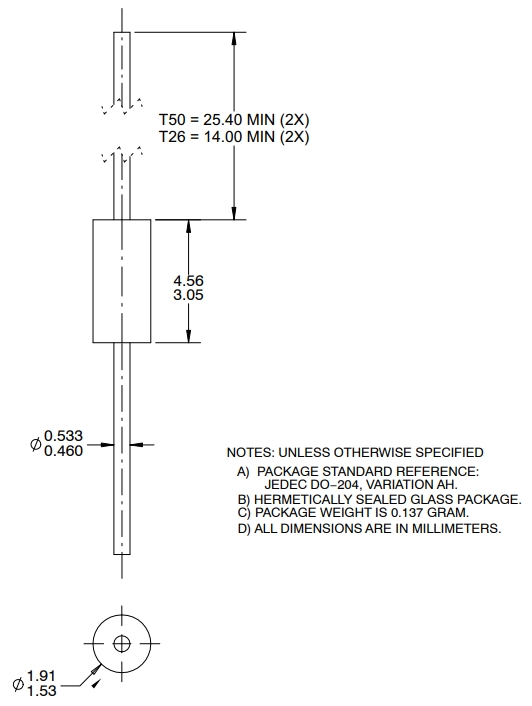
1N4148 Diode package
1N4148 Diode Datasheet PDF
For more detailed specifications and performance curves, consult the 1n4148 datasheet onsemi. The datasheet will provide more information on reverse leakage current, capacitance, and turn on voltage.
Related Information


-

-
Phone
+86 135 3401 3447 -
Whatsapp
